Navigation: Configuration > Configuration Guide (Web Mode) > Configuring Trunks > Configuring Signaling Data >
This topic describes how to configure an AT0 trunk connection between the unified gateway and the peer device.
Context
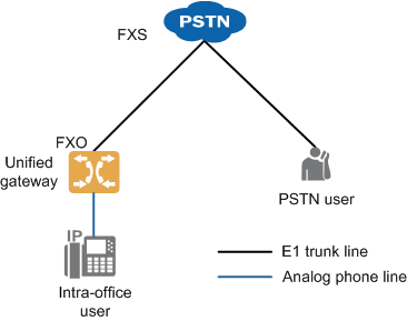
An AT0 trunk is an analog circuit trunk. It uses a analog subscriber line to connect an FXO port in the local office to an FXS port in the upper-level office to implement the dedicated line function. Figure 1 shows the network.
Figure 1 AT0 trunk network

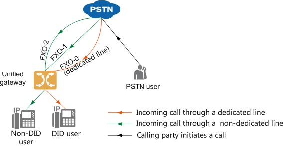
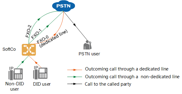
To support concurrent incoming and outgoing calls, you can apply to the local carrier for multiple lines, and allocate a number to each line. Based on the policy for using line resources, intra-office users are divided into DID users (that can occupy dedicated lines exclusively) and non-DID users. Table 1 describes the line selection rules in incoming and outgoing call scenarios.
Table 1 Line selection rules for AT0 trunks
Incoming and Outgoing Call Scenario |
Line Selection Rule |
Incoming call from a PSTN user |
Figure 2 shows the line selection rule. The calling party can dial the PSTN number corresponding to a dedicated line to directly call a DID user, or dial PSTN numbers corresponding to other lines to call any intra-office users through the automatic switchboard. Figure 2 Line selection rule for incoming calls
|
Outgoing call from an intra-office user |
When a DID user makes an outgoing call, the call must be routed through the dedicated line of the user. When a non-DID user makes an outgoing call, the system selects a line from other lines to route the call based on the line selection rule. Figure 3 shows the line selection rule. Figure 3 Line selection rule for outgoing calls
Available line selection rules for non-DID users include: ϒ⁄Ascending line selection The system selects lines from the line with the minimum ID in ascending order until an idle line is found. ϒ⁄Descending line selection The system selects lines from the line with the maximum ID in descending order until an idle line is found. ϒ⁄Polling The system selects lines from the line used in last AT0 outgoing call in ascending order until an idle line is found. When line FXO-11 is reached but no idle line is found, the system reselects lines from line FXO-0. |
Different countries and regions use different AT0 parameter standards (involving the signal tone, impedance, and CLIP signal mode). You need to adjust AT0 parameters when configuring an AT0 trunk to avoid problems such as call failures and low voice quality. Before the X1911/X1960/X1981 is delivered, AT0 signal tone and impedance parameters have been set for some countries including China, Australia, Brazil, United Kingdom, France, Germany, Ireland, Italy, Malaysia, Mexico, New Zealand, Russia, and Saudi Arabia. (By default, parameter settings for China are used.) You can switch AT0 parameter settings to standards in these countries or regions. If the country or region where the site is located is not included in the preset country/region list, check and adjust AT0 parameters by referring to Customizing AT0 Interface Parameters.
![]()
AT0 trunk calls are easily affected by noises if the device is not properly grounded. To improve call quality, ensure that the device is properly grounded. For details, see Grounding Guide.
Scenario Description
Configurations vary depending on the actual data plan. The following assumes that you need to:
ϒ⁄Enable a PSTN user to dial the number corresponding to line FXO-1 or FXO-2 to call automatic switchboard 8888, and dial an extension number as prompted to call an intra-office user.
ϒ⁄Enable a PSTN user to dial the number corresponding to line FXO-0 to directly call DID user 7000.
The following configurations are used as an example:
ϒ⁄You have added an OSU board on the device. For details, see Configuring Boards.
ϒ⁄You have added the user number 7000. For details on how to add a user number, see Allocating Numbers to SIP Users.
ϒ⁄You have added the switch number 8888. For details on how to add a switch number, see Product Documentation > Configuration > Feature Guide > Automatic Switchboard.
ϒ⁄You have added the office route 1. For details on how to add a switch number, see Configuring an Office Route.
Configuring the AT0 Trunk
1.Log in to the web management system. For details, see Logging In to the Web Management System.
2.Choose Trunk > Trunk Configuration > AT0 from the navigation tree.
a.Click the solid line between the AT0 trunk and the local office.
b.Click Create in the AT0 trunk configuration area, and set the parameters as shown in Figure 4.
Figure 4 Configuring the AT0 trunk

![]()
You can click the text box in the Port column to select and bind multiple FXO ports to the same office route. If you bind multiple FXO ports in different rows to the same office route, the same line selection mode and the same default called number must be used for them.
c.Click Create in the AT0 dedicated line configuration area, and set the parameters as shown in Figure 5.
Figure 5 Configuring the AT0 dedicated line

![]()
For the same FXO port, either the default called number or the dedicated line number must be configured. If the default called number and the dedicated line number are configured, the dedicated line number prevails.
d.Click OK.
e.Click Back to close the current window.
3.(Optional) Configure the AT0 country/region standards.
a.If the country or region where the site is located is included in the preset country/region list (China, Australia, Brazil, United Kingdom, France, Germany, Ireland, Italy, Malaysia, Mexico, New Zealand, Russia, and Saudi Arabia), perform the following steps to select the country or region. AT0 signal tone and impedance parameters are automatically set based on the local standards.
b.If the country or region where the site is located is not included in the preset country/region list or if you need to manually adjust more AT0 interface parameters, perform related operations on the following web portals. For details, see Customizing AT0 Interface Parameters.
![]()
If you change the Country or Region value, you must restart the device for the preset AT0 parameters to take effect.
4.(Optional) Add a number sign (#) to called numbers of the calls that are initiated by SIP users and routed to external users through AT0 trunks.
By default, called numbers of calls that are initiated by SIP users and routed to external users through AT0 trunks do not contain a number sign (#). If the peer office requires that the called number be ended with a number sign (#), it will not connect such calls until the timeout duration expires. To enable the peer office to connect such calls without any delay, perform the following steps.
a.Choose Trunk > Trunk Configuration > AT0 > Global.
b.Click Configure next to Advance in the window that is displayed. The window shown in Figure 7 is displayed.
Figure 7 Enabling the system to automatically add a number sign (#) to called numbers for calls initiated by SIP users and routed to external users through AT0 trunks

c.Set Add # for outgoing calls in Figure 6 to Yes.
Verification
Task |
Operation |
Result |
Verify outgoing calls. |
An intra-office user dials the number of a PSTN user. |
The call is connected properly. |
Verify the AT0 dedicated line function. |
A PSTN user dials the number corresponding to line FXO-0. |
Intra-office user 7000's phone rings. |
Verify the AT0 switchboard function. |
A PSTN user dials the number corresponding to line FXO-1 or FXO-2. |
The PSTN user hears the announcement of automatic switchboard 8888. |
Troubleshooting
If the call fails, see AT0 Trunk Faults.
Parent Topic: Configuring Signaling Data

