Navigation: Configuration > Configuration Guide (Web Mode) > Verifying the CDR Service >
On the CDRServer, configure the data for interworking with the unified gateway and the information related to CDR storage.
1.Log in to the CDRServer.
2.Set the unified gateway to connect as an authenticated unified gateway.
a.Click ![]() in the system tray of the CDRServer.
in the system tray of the CDRServer.
The CDR Server window is displayed.
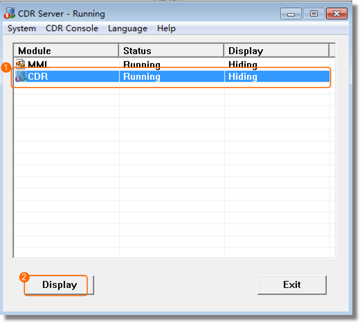
b.Select CDR and click Display, as shown in Figure 1.
Figure 1 CDR Server CDR-Running

c.Choose Control > Unified Gateway Authorize, and configure the authentication account and password.
By default, authentication is used when the CDRServer connects to the unified gateway. To ensure data transmission security, it is recommended that authentication be enabled. The default account is admin and the default password is admin123. It is recommended that you periodically change the password and use a complex password.
![]()
When authentication is enabled, you must also set the authentication mode to AuthByPwd on the X1900 series unified gateway. Otherwise, connections cannot be established between the X1900 and CDRServer.
The account and password here must be the same as the account and password configured on the X1900 series unified gateway.
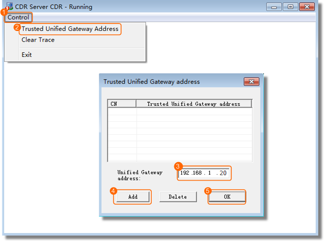
d.Choose Control > Trusted Unified Gateway address. Enter the IP address of the unified gateway in the Unified Gateway address text box and click Add, as shown in Figure 2.
ϒ⁄You need to add IP addresses of all unified gateways in a single-node, multi-node centralized, or multi-node distributed (peer-to-peer) network.
ϒ⁄You need to add IP addresses of all unified gateways (excluding the convergent gateway) in a multi-node distributed (convergent) network.
Figure 2 Adding Unified Gateway address

e.Click OK.
A message is displayed, prompting you to restart the CDR service for the configuration to take effect.
f.Click OK.
3.Set the path for storing CDR files.
a.In the CDR Server window, choose CDR Console > Control call record file path.
The Config call record file path dialog box is displayed.
b.Set the CDR file path (D:\ in this example).
![]()
The system will automatically place the binary CDR files to the $\Bill\CufFile directory (D:\Bill\CurFile in this example). The variable $ is the CDR file path you have set.
When the unified gateway has any call services, the system automatically generates D:\BillL\CurFile and D:\Bill\BakFile directories on the CDRServer.
ϒ⁄The D:\Bill\BakFile directory stores backup binary CDR files.
c.Click OK.
4.Gnerate text bill (Option).
UScale ECS V2.0 and later version, the system supports to generate text CDR files.
In the CDR Server window, choose CDR Console > Generate Text Bill or Not > Yes.
The system generates both text CDR and binary CDR files. The system will automatically place the text CDR files to the $\Bill\TxtBills directory (D:\Bill\TxtBills in this example). The variable $ is the CDR file path you have set.
Text CDRs are provided for third-party billing systems to read and parse. The BMU cannot parse text CDRs.
5.Restart the CDRServer.
a.Close the CDR Server CDR-Running window.
b.In the CDR Server window, click Exit to exit the CDRServer.
c.Double-click ![]() to start the CDRServer.
to start the CDRServer.
6.Install and configure the FTP or FTPS service on the CDRServer.
![]()
The CDRServer cannot be deployed on the same server as eSight or use the FTP service provided by eSight; otherwise, the BMU may obtain CDRs repeatedly.
Parent Topic: Verifying the CDR Service