Navigation: Configuration > Configuration Examples in Typical Scenarios > Multi-Node Network Scenario (Peer-to-Peer) >
This topic describes the data plan for node interconnection to implement voice communication between different nodes.
Service Requirements
This topic assumes the following number segments as the planned ones in the current network scenario:
ϒ⁄Node 1: 80000-89999
ϒ⁄Node 2: 70000-79999
ϒ⁄Node 3: 60000-69999
Voice calling between users at three nodes needs to be implemented.
Prefix Plan
NE |
Prefix |
Call Attribute |
Office Route Selection Code |
Calling Number Change |
Called Number Change |
Display Calling Party's Long Number (Yes/No) |
Remarks |
Node 1 |
7 |
Local call |
12 |
- |
- |
No |
Outgoing call prefix, used for calling users at node 2. |
6 |
Local call |
13 |
- |
- |
No |
Outgoing call prefix, used for calling users at node 3. |
|
Node 2 |
8 |
Local call |
21 |
- |
- |
No |
Outgoing call prefix, used for calling users at node 1. |
6 |
Local call |
23 |
- |
- |
No |
Outgoing call prefix, used for calling users at node 3. |
|
Node 3 |
8 |
Local call |
31 |
- |
- |
No |
Outgoing call prefix, used for calling users at node 1. |
7 |
Local call |
32 |
- |
- |
No |
Outgoing call prefix, used for calling users at node 2. |
Trunk Plan
NE |
Trunk Type |
Office Route Number |
Peer Device |
Destination IP Address |
Destination Port |
Node 1 |
SIP |
12 |
Node 2 |
10.20.1.2 |
5060 |
SIP |
13 |
Node 3 |
10.30.1.2 |
5060 |
|
Node 2 |
SIP |
21 |
Node 1 |
10.10.1.1 |
5060 |
SIP |
23 |
Node 3 |
10.30.1.2 |
5060 |
|
Node 3 |
SIP |
31 |
Node 1 |
10.10.1.2 |
5060 |
SIP |
32 |
Node 2 |
10.20.1.2 |
5060 |
Configuration Process
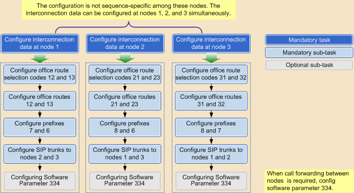
Figure 1 illustrates the configuration process based on the preceding requirements and data plan.
Figure 1 Process for configuring node interconnection

Parent Topic: Multi-Node Network Scenario (Peer-to-Peer)