Navigation: Configuration > Configuration Examples in Typical Scenarios > Multi-Node Network Scenario (Peer-to-Peer) >
Enterprise users in the organizations register with the respective local node. Different nodes are interconnected using SIP trunks to implement inter-node voice communication.
Network Scheme
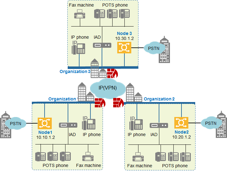
Figure 1 illustrates the peer-to-peer network adopted between multiple nodes.
Figure 1 Network scheme

Network Description
ϒ⁄Each organization deploys a unified gateway as a node, which can be UScale X1911, X1960, X1981.
ϒ⁄IP phones, POTS phones, and fax machines all register with the unified gateway in the local organization. The unified gateways in different organizations can connect to the PSTN using trunks such as PRA, SS7, QSIG, R2, and AT0 for local outgoing calls.
ϒ⁄Different nodes are interconnected using SIP trunks. The peer-to-peer network mode supports interconnection between two or three nodes.
Inter-Office Call Routing
Figure 2 Inter-office call routing

At each node, configure office routes, outgoing call prefixes, and SIP trunks to the other nodes for implementing voice communication between these nodes.
ϒ⁄When user 80001 at node 1 calls user 70001 at node 2, node 1 analyzes the number and according to the analysis result (7 is the call prefix to node 2), routes the call to node 2. Then, node 2 connects the call to user 70001, as indicated by ![]() in Figure 2.
in Figure 2.
ϒ⁄When user 80001 at node 1 calls user 60001 at node 3, node 1 analyzes the number and according to the analysis result (6 is the call prefix to node 3), routes the call to node 3. Then, node 3 connects the call to user 60001, as indicated by ![]() in Figure 2.
in Figure 2.
Parent Topic: Multi-Node Network Scenario (Peer-to-Peer)