The UCP2120 chassis provides a centralized and interconnected space for internal components while preventing component contamination and protecting them from external causes of damage.
Appearance
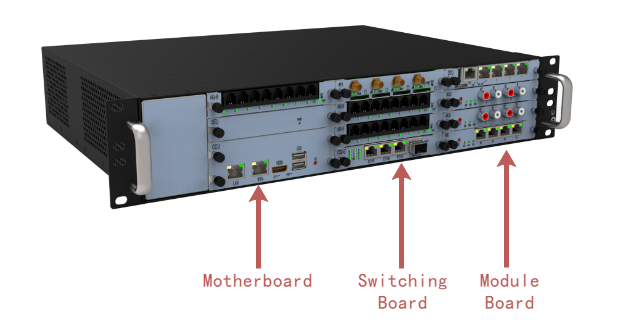
The UCP2120 is a 2U standard chassis, 434mm wide, 330mm deep and 88mm high. The chassis can be installed in an IEC (International Electrotechnical Commission) compliant 19-inch cabinet, and its appearance is shown in Figure 1.
Figure 1 Chassis appearance
Slot
The slots are located on the front side of the chassis, and the UCP2120 provides two main control board slots and nine service board slots.
•Slots 2-11 are service board slots for installing various service boards and support mixed plugging.
•Slot 1 and 8 are the master board slots for installing CCU series master boards and support dual master control.
•If CCU-N-GML main control board wants to expand the hard disk board, you can insert the hard disk board into slot 3/10. For example, if the main control board is in slot 1, the hard disk board can be placed in slot 3; if the main control board is in slot 8, the hard disk board can be placed in slot 10.
•If CCU-N-BAYL, CCU-I-KABYLR main control board want to expand the hard disk board, you can insert the hard disk board to slot 3-4. For example, the main control board is in slot 1, the hard disk board can be placed in slot 3 and 4; the main control board is in slot 8, the hard disk board can be placed in slot 10 and 11.
The slot distribution is shown in Figure 2.
Figure 2 Chassis slot distribution
4 |
7 |
11 |
|---|---|---|
3 |
6 |
10 |
2 |
5 |
9 |
1 |
CSU-F/G |
8 |
Description:
•The UCP2120 interface board can be optional depending on the system capacity. Empty slots that are not configured with interface boards require the installation of empty panels.
•To ensure the normal use of basic functions, the UCP2120 needs to be equipped with one main control board.
•The M4 grounding screw is not required if the device is mounted on the cabinet using lug screws; the M4 grounding screw is required if the chassis is mounted on a pallet without lug screws for grounding.
•The service board will identify the initial IP address based on the slot number, for example, slot 2: 172.16.80.2
•CCU-N-BAYL uses on-board mSATA by default, expandable HDD board, refer to CCU-N-GML.
•CCU-I-KABYLR main control board occupies 2 slots, CCU-N-GML and CCU-N-BAYL occupy one slot.
Parent topic: UCP1600/2120/4131 Product Structure