The UCP4131 chassis provides a centralized and interconnected space for internal components while preventing component contamination and protecting them from external causes of damage.
Appearance
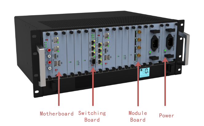
The UCP4131 is a 4U standard chassis, 435.8mm wide, 330mm deep and 176.8mm high. The chassis can be installed in an IEC (International Electrotechnical Commission) compliant 19-inch cabinet, and its appearance is shown in Figure 1.
Figure 1 Chassis appearance
Slot
The slots are located on the front of the chassis, and the UCP4131 provides 2 slots for main control boards, 9 slots for interface boards, and 2 slots for power supplies.
•Slots 1, 3 to 6, and 8 to 11 are service board slots for installing various module boards and support mixed plugging.
•Slots 2 and 7 are master board slots for installing CCU boards and support dual master control.
•For the case of no RAID module:
① CCU-N-GML main control board wants to expand the hard disk board, it can support 1 hard disk board. If the main control board is in slot 2, you can plug the hard disk board into slot 1; if the main control board is in slot 7, you can plug the hard disk board into slot 6.
② CCU-N-BAYL and CCU-I-KABYLR main control boards want to expand the hard disk board and can support up to 2 hard disk boards. If the main control board is in slot 2, you can plug the hard disk board into slot 1 and 4; if the main control board is in slot 7, you can plug the hard disk board into slot 6 and 9.
•For accessing the RAID module:
① CCU main control board is inserted into slot 2, if you want to expand RAID, the RAID card is inserted into slot 4, and the RAID hard disk is inserted into slots 3 and 5.
② The CCU main control board is inserted into slot 7, if you want to expand the RAID, the RAID card is inserted into slot 9 and the RAID hard disk is inserted into slots 8 and 10.
The slot distribution is shown in Figure 2.
Figure 2 Chassis slot distribution
service board
1 |
control board
2 |
service board
3 |
service board
4 |
service board
5 |
Switching Board
CSU-F/G |
service board
6 |
control board
7 |
service board
8 |
service board
9 |
service board
10 |
service board
11 |
|
power supply
12 |
power supply
13 |
Description:
•When only one master board is installed in the two master board slots, the system runs in single master mode; when the two master board slots are fully configured, the system runs in master-standby master mode, which has higher reliability.
•The UCP4131 interface board can be optional according to the system capacity. Empty slots that are not configured with interface boards or power supplies require the installation of empty panels.
•To ensure the proper use of basic functions, the UCP4131 is equipped with at least 1 master board.
•CCU-N-BAYL uses on-board mSATA by default and can be expanded with a hard disk board, refer to CCU-N-GML.
•CCU-I-KABYLR main control board occupies 2 slots, CCU-N-GML and CCU-N-BAYL occupy one slot.
Parent topic: UCP1600/2120/4131 Product Structure