Navigation: Fault Management > Troubleshooting Guide > Trunk Faults > Background >
The SS7 trunk includes the ISUP signaling.
TUP signaling process
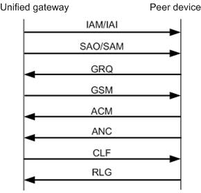
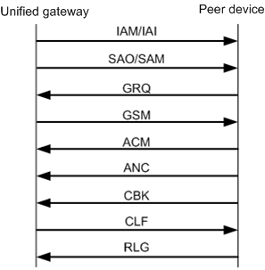
ϒ⁄Figure 1 and Figure 2 show the normal signaling process.
Figure 1 Normal TUP signaling process (intra-office user first hangs up)

Figure 2 Normal TUP signaling process (peer user first hangs up)

The normal signaling process is as follows:
1.When intra-office user calls peer user, unified gateway device sends an IAM message or an IAI message containing the information about initial address.
2.unified gateway device sends an SAO message or an SAM message containing the information about peer user address.
3.If other information is required for connecting the call, peer device sends a GRQ message requesting other information.
4.After receiving the GRQ message, unified gateway device encapsulates the required information into a GSM message. Then the GSM message is sent. In this case, all the information required for establishing the call is collected.
5.Peer device locates the user according to the information and sends an ACM message. Intra-office user plays the RBT and peer user phone rings.
6.After peer user picks up the phone, unified gateway device sends an ANC message indicating that peer user has picked up the phone.
7.Intra-office user starts to talk with peer user.
8.The mode of sending messages according to the hangup sequence.
ϒ⁄If intra-office user first hangs up, unified gateway device sends a CLF message indicating that intra-office user has hung up.
ϒ⁄If peer user first hangs up, peer device sends a CBK message indicating that peer user has hung up. Then intra-office user hangs up and sends a CLF message.
9.Peer device sends an RLG message indicating that peer device is informed that intra-office user has hung up.
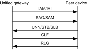
ϒ⁄Figure 3 shows the call failure signaling process.
Figure 3 TUP call failure signaling process

When a user in office A (user A) fails to call a user in office B (user B), the device in office B will send a message to user A based on the user B status.
1.If the called number is null, the device sends a UNN message to the unified gateway.
2.If the called number is busy, the device sends a subscriber toll busy signal (STB) or subscriber local busy signal (SLB) to the unified gateway.
ISUP signaling process
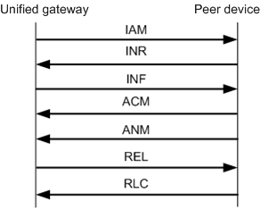
ϒ⁄Figure 4 shows the normal ISUP signaling process.
Figure 4 Normal ISUP signaling process

The normal ISUP signaling process is as follows:
1.When intra-office user calls peer user, intra-office users sends an IAM message containing the information about peer user address.
2.Peer device returns an INR message containing other information required for establishing the call.
3.unified gateway device sends an INF message containing the information required for establishing the call.
4.Peer user device locates the user according to the information and sends an ACM message. intra-office user plays the RBT and peer user phone rings.
5.Peer user sends an ANM message indicating that peer user has hung up.
6.Intra-office user starts to talk with peer user.
7.If intra-office user first hangs up, unified gateway device sends an REL message indicating that intra-office user has hung up.
8.peer device device sends an RLC message indicating that peer device is informed that intra-office user has hung up.
Parent Topic: Background