Navigation: Fault Management > Emergency Maintenance > Common Operations > Replacing Parts >
This topic describes the process of replacing a board.
Precautions
For the X1911/X1960/X1981, the devices and boards from V200R003C00 have different default internal IP network segments from those in earlier versions. Table 1 lists the differences (x in the table indicates the slot number).
Table 1 Differences between versions
Version |
Default Internal IP Network Segment |
How to Change the Internal IP Network Segment |
Versions earlier than V200R003C00 |
ϒ⁄168.168.0.1x This network segment is a public IP network segment. Although I/O boards cannot directly communicate with the service/management network, it is recommended that their internal IP network segment be changed to the private IP network segment. ϒ⁄168.168.255.255 Used in the broadcast network communication between boards. |
When switching the internal IP network segment, the slot number needs to be specified. The switching operation needs to be performed on all existing I/O boards (excluding ASI and OSU) and active and standby control boards. ϒ⁄Other models: config inner network ip <A.B.C.D> [slot <slot>] |
V200R003C00 and later versions |
172.20.0.1x |
The slot number does not need to be specified when the internal IP network segment is switched. ϒ⁄Other models: config inner network ip <A.B.C.D> |
If the internal IP network segment of existing boards on the device is different from that of a new board, the new board will fail to function properly due to an internal communication error. Before replacing a board, take appropriate approaches according to the device model to avoid a board failure after replacement.
ϒ⁄For the X1911/X1960/X1981, you do not need to switch the internal IP network segment before board replacement. The internal IP network segment of the new board will be automatically changed to the same as that of the control board.
ϒ⁄The internal IP network segment of the new board will be automatically changed to the same as that of the control board; otherwise, manually change the internal IP network segment of existing boards to 168.168.0.1x or 172.20.0.1x before board replacement.
![]()
ϒ⁄The internal IP network segment of boards cannot conflict with the IP network segment of any management or service network port on the device at any time. If conflict occurs, the system communication fails. If the communication failure occurs, you need to change the IP address of the network port by connecting to the device using the serial port.
ϒ⁄The internal IP network segment does not change after an upgrade from an earlier version to V200R003C00.
ϒ⁄If the status of a new board is displayed as Fault, run the reset board slot slot command to restart the board.
Confirming the Operation Feasibility
Before replacing a board on the device for rectifying a fault or maintaining the device, confirm the operation feasibility according to the following points:
ϒ⁄The spare board is available in the warehouse.
ϒ⁄You are familiar with the process of replacing the board.
Obtaining the Spare Part and Tools
After confirming the operation feasibility, obtain a spare board, an ESD wrist strap, and a Phillips screwdriver.
Confirming the Position of the Board to Be Replaced
Before removing the board to be replaced, confirm the slot where the board is installed. Locate the board, and attach a label to the board panel for identification.
Removing the Original Board
1.Remove cables from the board.
2.Use a screwdriver to loosen the captive screws on the board panel anticlockwise.
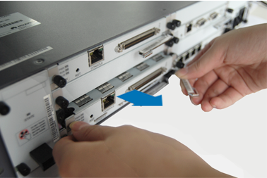
3.Turn the ejector lever outwards to loose the connection of the board connector from the backplane connector, as shown in Figure 1.
Figure 1 Removing the board (using X1960 as an example)

4.Remove the board along the guide rail.
5.Keep the board properly for repair.
Installing the New Board
1.Take the board out from an ESD bag.
2.Put the front end of the board into the slot where the old board is installed.
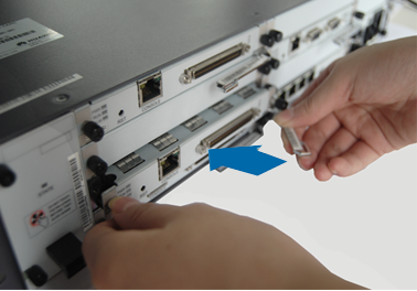
3.Insert the board along the guide rail, as shown in Figure 2.
Figure 2 Inserting the board (using X1960 as an example)

4.Turn the ejector lever inwards to securely connect the board to the backplane.
5.Use a screwdriver to fasten the captive screws clockwise and secure the board.
After replacement, ensure that the surface of the board is at the same plane as that of other boards.
6.Connect the cables to the newly installed board.
Checking the Running Status of the New Board
After being inserted into the shelf, the board automatically communicates with the main control board in the shelf. You can check whether the board is functioning properly by observing the indicator status. For details about how to check the indicators, see the Checking Equipment Indicators.
Returning the Faulty Board for Repair
After replacing the faulty board, contact OpenVox technical support engineers for repair.
Parent Topic: Replacing Parts