D830P/E DE830P/E Hardware Manual
Safety Instructions
1. (a) The D830P/E DE830P/E is subject to specific national safety regulations during application.
2. Turn off the power before installing the D830P/E DE830P/E.
3. To prevent damage to the board by electrostatic induction, snap the card stopper to the PC with a screw
on the PC to achieve grounding.
4. (b) The electrostatic ring is essential during installation.
5. Please follow the instruction steps.
Chapter 1 Overview
1.1 D830P/E DE830P/E Introduction
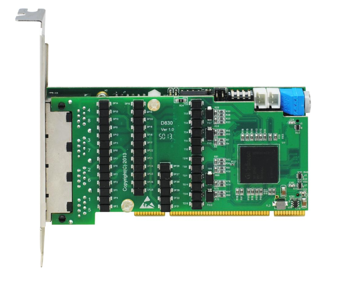
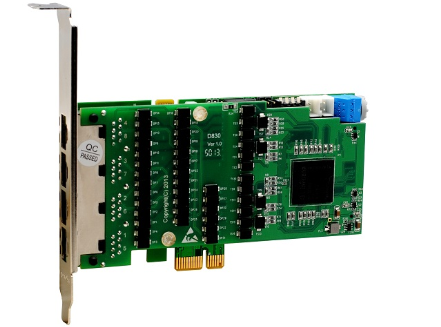
The D830P/E DE830P/E is the most advanced 8-port T1/E1/J1 PCI interface voice card available in the open source community and offers the highest quality voice calls. The advanced innovation of this product not only ensures users to reduce system CPU usage by up to 70% after adjusting the interrupt frequency, but also modifies the product interrupt number to avoid interrupt number sharing or conflicts.DE830 consists of the D830 and a hardware echo cancellation module based on the Octasic® chip. T1, E1 and J1 modes can be freely selected for each card and even for each physical port. The Octasic® chip-based hardware echo cancellation module can eliminate echo tails up to 128ms or 1024taps on 256 channels in E1 mode or 192 channels in T1/J1 mode. the module takes full advantage of the Octasic® voice quality improvement feature to ensure perfect sound quality on every call. The D830P/E DE830P/E supports industry standard telephone line and data protocols, including PRI ISDN (North American and European standards) protocols, PPP, Cisco, HDLC and Frame Relay data modes, as well as line and trunk interfaces.
The D830P/E DE830P/E supports Asterisk®, Issabel, FreeSWITCH™, Yate™ and other IPPBX/IVR open source project applications.
Typical Applications
- High-performance ISDN BRI voice boards
- VoIP services
- IVR Applications
- “Meet-Me” Conference Bridge
- Calling Card Platform
- VoIP gateways (SIP, H.323, and IAX support)
- Traditional PBX/IVR services
- Voice and data routers
Chapter 2 Hardware Installation
2.1 Channel Type Setting
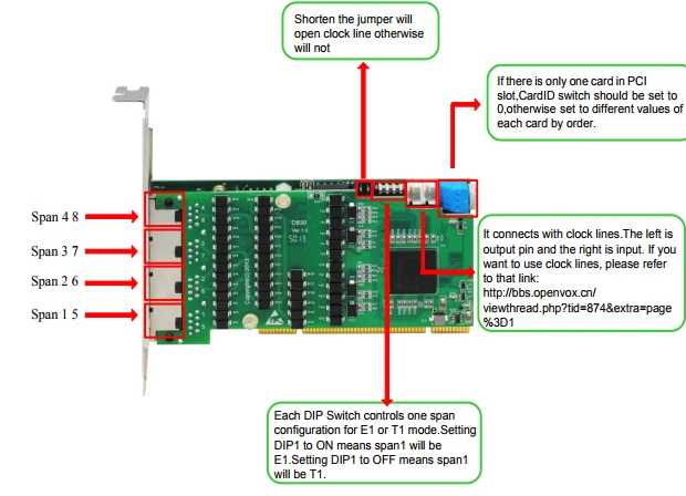
Each DIP switch controls the mode of a channel. By setting the DIP switch, the channel can be set to E1 or T1 mode. When DIP1 is set to ON, it means channel one is E1 mode, and when DIP1 is set to OFF, it means channel one is T1 mode.
2.2 Card ID Setting
If there is only one card on your machine, the value corresponding to the knob should be set to 0. If two D830P/E or DE830P/E are installed at the same time, which means two identical cards are installed, the CardID of the card closest to the CPU should be set to “0 The CardID of the card closest to the CPU should be set to “0”, the card farther away should be set to “1”, and so on. The default state of the knob is 0.
2.3 Slot
D830P/DE830P is compatible with industry standard 32-bit 5.0V, 64-bit 3.3V and 64-bit 5.0V PCI slots, not compatible with any type of PCI-E slots. Users first need to confirm the slot type and insert the D830P/DE830P vertically into any of the above PCI slots. The following figure depicts the four slot shapes.
D830E/DE830E is compatible with industry standard PCI-E ×1, PCI-E ×2, PCI-E ×4, PCI-E ×8, and PCI-E ×16 slots, and is not compatible with any type of PCI slots. Users first need to confirm the slot type and insert the D830E DE830E vertically into any of the above PCI-E slots. The following figure depicts the four slot shapes.
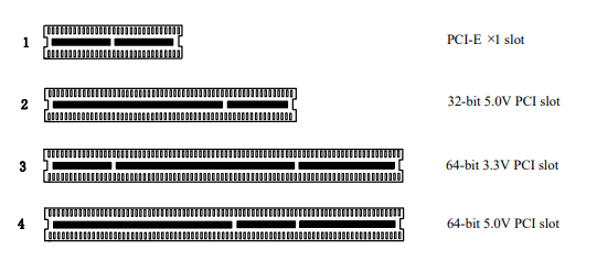
Figure 1 PCI and PCI-E slots
2.4 Clock Lines
If the user has only one card, then all the channels on this card run at the same clock frequency, at this point, no clock lines are needed. If the user installs multiple cards on a machine at the same time, clock lines can provide many benefits. If clock lines are not used, each card runs at its own clock frequency to send and receive data, at which point accuracy is compromised. In voice data, this problem is negligible, but in data transmission such as fax and modem, it can lead to incalculable impact. Data loss will cause communication interruptions or even crashes. Clock lines allow all cards to operate under the same clock source, sending and receiving data at the same rate, without data loss.
If the user can find J914 (input) and J915 (output) interface on the card, it means this card supports clock line.
Other functions
Users can run “ cat /proc/interrupts “ command to see if the D830P/E DE830P/E has independent interrupts. if the D830P/E DE830P/E shares interrupts with other devices, it will cause some problems. the D830P/E DE830P/E supports changing the interrupt pin number during firmware upgrade to avoid conflicts. You can check if the EC module is working by using the following command.
2.5 EC module identification and its enable
After completing the installation and configuration by referring to the software installation manual of the corresponding board, execute the command “dmesg | grep VPM” to check if the EC module is available.
[root@localhost ~]# dmesg | grep VPM
VPM450: echo cancellation for 256 channels
opvxd115 0000:20:00.0: VPM450: hardware DTMF disabled.
opvxd115 0000:20:00.0: VPM450: Present and operational
servicing 2 span(s)
Chapter 3 Reference List
www.openvox.cn
www.digium.com
www.asterisk.org
www.voip-info.org
www.asteriskguru.com
Warm Tips.
Users who encounter any problems during installation and use, please find answers and leave comments on OpenVox forum or wiki.
Appendix A Hardware Specifications
– Weight, Size
Weight: 98g(D830E) 20g(EC2032)
Size: 2U Form Factor: 12×6.4×1.6cm 3
– Interface
RJ48 interface
PCI 3.3V or 5V PCI 2.2 or higher
PCI-E PCI-E ×1, PCI-E ×2, PCI-E ×4, PCI-E ×8 and PCI-E ×16 slots
– Environment
Storage temperature: -65 ~ 125°C (D130P) -40 ~ 75°C (EC2032)
Operating temperature: 0 ~ 50°C
Humidity: 10 ~ 90% non-condensing
– Power Consumption
Voltage: 3.3V, 5V
Power loss: 2.6W (min) 3.9W (max)
-Hard and software configuration requirements
RAM 128+ MB
Linux kernel 2.4.X or 2.6.X
CPU 800+ MHz
Appendix B Hardware Disassembly Diagram
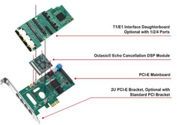
The hardware disassembly diagram of D830P/DE830P is similar to that of D830E/DE830E, and the D830E/DE830E disassembly diagram is shown below.
Appendix C Jumper and Switch Settings
Appendix D Splitter
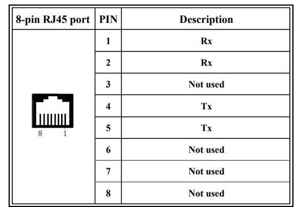
The D830P/E DE830P/E requires a splitter to divide each 8-pin RJ45 interface into two 4-pin E1 interfaces, as shown in the following pin assignment.
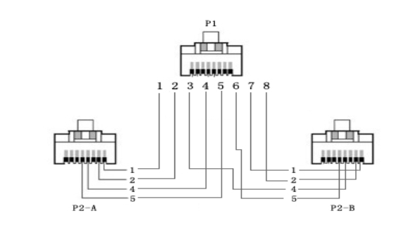
D830 splitter P1 end RJ45 interface
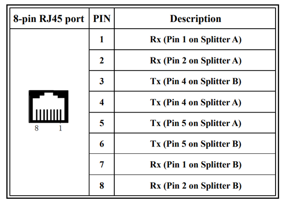
DE830 series splitter P2-A and P2-B end RJ45 interface
