B100P/E Hardware Manual
Safety Instructions

- (a) The B100P/E is subject to specific national safety regulations during application.
- Turn off the power before installing the B100P/E.
- (b) To prevent damage to the board by electrostatic induction, snap the card stopper to the PC with screws for grounding.
- (b) Static ring is essential during installation.
- Please follow the instruction steps.
Chapter 1 Overview
1.1 Introduction of B100P/E
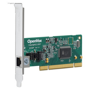
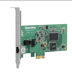
The OpenVox B100P/E is a PCI or PCI-E slot compatible board that supports a BRI S/T interface that can be set to TE or NT mode via jumpers. The B100P/E is used to build Asterisk-based open source systems like ISDN telephony switching systems and VoIP voice gateways.
The B100P/E runs well on open source operating systems such as Asterisk®, Issabel, FreeSWITCH™, Yate™ and IPPBX/IVR to deliver clear voice. It can be used as a PBX, IVR, and VoIP gateway.
Typical applications
- High performance ISDN BRI voice boards
- ISDN BRI private automatic switch
- ISDN BRI Network Routing
- VoIP Voice Gateway
- ISDN PBX Trunking
- ISDN BRI Test Equipment
Key Features
- Integrated one S/T interface
- Supports PCI-E 1.0 and above specifications, provides 3.3/12V voltage
- ITU-T I.430 and TBR 3 certified
- Supports TE/NT mode
- DTMF detection for each B-channel
- Multi-party voice conference bridging
- Low power design
- Fully compatible with Junghanns.NET ISDN, mISDN driver, DADHI and other drivers
- RoHS
Certified
- CE, FCC, A-Tick
- Issabel
Chapter 2 Hardware Installation
2.1 Power Supply
The board requires only 3.3/12V from the PCI-E slot when operating in TE/NT mode, no external power supply is required.
2.2 Slot
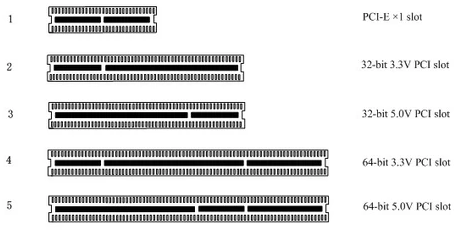
The B100P is compatible with industry standard PCI slots. Users first need to confirm the slot type and insert the B100P vertically into any of the PCI slots. The following diagram depicts the five slot shapes.
The B100E is compatible with industry standard PCI-E ×1, ×2, ×4, ×8 and ×16 slots. Users should first confirm the slot type and insert the B100E vertically into any of the PCI-E slots. The following diagram depicts the five slot shapes.

Figure 1 PCI and PCI-E Slots
2.3 Adjusting the Terminal S/T Interface Mode
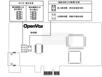
The interface of B100P/E can be set to NT or TE mode, please refer to the following figure.
- (a) If the interface needs to work in NT mode, the jumper should be set to Connect.
- If working in TE mode, the jumper should be set to disconnect in theory, but the B100P/E may be connected to some non-standard ISDN terminal devices, which do not have terminal resistors, and the jumper should be set to connect in this case.

Figure 2 B100P/E jumper setting
2.4 Hardware installation steps
- Power off the computer, remembering to disconnect the AC power cord.
- Make sure that the jumpers are set correctly.
- Insert the B100P/E vertically into the PCI-E slot.
- Plug the ISDN line into the RJ-45 connector set to TE mode and the ISDN phone line into the RJ-45 connector set to NT mode.
- Secure the card to the chassis with screws.
- Plug in the power cable and power on.
Note: If you need to connect an ISDN phone to a B100P/E set to NT mode, the phone must be self-powered. The static ring is essential during the above operation and installation or removal of the board should only be done after a power failure. After making sure the hardware is installed correctly, the software installation can begin.
Chapter 3 Reference Table of Contents
Warm Tips.
If users encounter any problems during installation and use, please find answers and leave messages on OpenVox forum or wiki.
Appendix A Hardware Specifications
– Weight, Size
Weight(g) : 51
Size(mm): 120×688×18
– Interface
B100P PCI interface
B100E PCI-E 1.0+ specification
Interface type: 4-pin RJ-45 connector, providing an S/T interface
-Environment
Temperature: 0 ~ 50°C (operating)
– 40 ~ 125°C (Storage)
Humidity: 10 ~ 90% non-condensing
-Power consumption
Voltage: 3.3V, 38V (NT mode)
Power loss: 0.4W (min.), 0.57W (max.)
– Hardware and software configuration requirements
RAM 128 + MB
Linux kernel 2.4.X or 2.6.X
CPU 800+ MHZ
Appendix B RJ45 Pin Assignment
ISDN BRI has two kinds of interfaces: U interface and S/T interface. B100P/E provides four-pin S/T interface. We illustrate the pin assignments with the following two tables.
l ISDN U interface
| 8-pin RJ45 connector | Pins | Color | Description |
| 1 | White/Orange | N/A | |
| 2 | Orange | N/A | |
| 3 Orange | White/Green | N/A | |
| 4 | Blue | U interface | |
| 5 | White/Blue | U interface | |
| 6 | White | N/A | |
| Green | White/Brown | -48VDC Power (optional) | |
| White | Brown | -48VDC Return (optional) |
The ISDN U interface is typically used in North American ISDN networks and uses a standard 8-pin RJ45 connector, but only the center two pins (4 and 5) are used, forming a two-conductor crossover. The optional -48 VDC power pin can be defined by pins 7 and 8 of the RJ-45. This can be used to power NT-1 or TE devices when needed. In most cases, the telephone company does not provide a feed.
l ISDN S/T Interface
| 8-pin RJ45 connector | Pin | Color | Description |
| 1 | White/Orange | N/A | |
| 2 | Orange | N/A | |
| 3 Orange | White/Green | Receive+ | |
| 4 | Blue | Transmit + | |
| 5 | White/Blue | Transmit – | |
| 6 | Green | Receive – | |
| 7 | White/Brown | -48VDC Power(optional) | |
| 8 | Brown | -48VDC Return (optional) |
The ISDN S/T interface also uses a standard 8-pin RJ45 connector, but only four of the pins (3, 4, 5 and 6) are used, forming a four-core straight-through line. Of these, 4 and 5 are used for transmit and 3 and 6 are used for receive. The optional -48 VDC power pins can also be defined by pins 7 and 8 of the RJ-45 and are used to power NT-1 or TE devices when needed.


