A810P/E AE810P/E Hardware Manual
Safety Instructions
- (a) The A810P/E AE810P/E is subject to specific national safety regulations during application.
- Turn off the power before installing the A810P/E or AE810P/E.
- (b) To prevent damage to the board by electrostatic induction, snap the card stopper to the PC with screws for grounding.
- (b) The electrostatic ring is essential during installation.
- Please follow the instruction steps.
Chapter 1 Overview
1.1 A810P/E AE810P/E Introduction
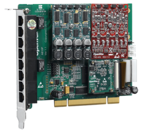
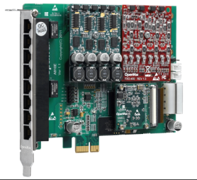
The OpenVox A810P/E and AE810P/E are green and lead-free 8-port FXO/FXS analog interface products, and the AE810P/E is an A810P/E with Octasic hardware echo cancellation module. The A810P/E AE810P/E has 8 RJ11 connectors on the board, each allowing access to 1 analog signal.
The A810E/AE810E can run on Asterisk®, Issabel, FreeSWITCH™, Yate™ and IPPBX/IVR open source operating systems to deliver clear voice for SOHO or SMB PBX, IVR, and VoIP gateway applications.
Typical Applications
When you need to access four PSTN lines and four analog telephones, you can install the modules according to the following diagram: FXS module corresponding interface to the telephones and FXO module corresponding interface to the PSTN lines.
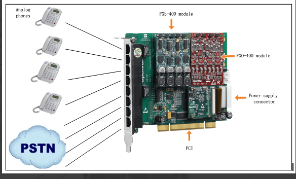
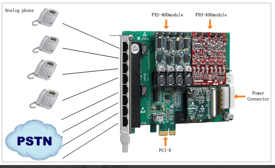
Figure 2 Typical Application
Key Features
- Worldwide availability
- Superior hardware design and stability
- FPGA design with field upgradeable firmware
- Supports interrupt pin selection, interrupt frequency modification to avoid interrupt sharing
- Support for Bus Master operation at speeds up to 132 Mbytes/sec.
- Highly stable firmware enables I/O acceleration and greatly reduces CPU load
- Scalability: if users need more ports, they only need to install the appropriate type of board
- Support for the industry’s highest quality Octasic echo cancellation DSP, with independent 128ms or 1024taps per channel echo cancellation
- RoHS
certification
- CE, FCC, A-Tick
- Issabel
Chapter 2 Hardware Installation
2.1 Power Supply
Since the PCI or PCI-E slot cannot provide the required power for FXS-400, FXO-400, the user needs to provide an external power supply to the board through the 12V 4-PIN connector. If no external power supply is provided, the module will not be recognized by the system.
2.2 Slots
The A810P/AE810P is compatible with industry standard 32-bit 5.0V, 64-bit 3.3V and 64-bit 5.0V PCI slots, and is not compatible with any type of PCI-E slots. Users should first confirm the slot type and insert the A810P/AE810P vertically into any of the PCI slots. The following figure depicts the four slot shapes.
A810E/AE810E is compatible with industry standard PCI-E ×1, PCI-E ×2, PCI-E ×4, PCI-E ×8, and PCI-E ×16 slots, and is not compatible with any type of PCI slots. Users first need to confirm the slot type and insert the A810E/AE810E vertically into any of the PCI-E slots. The following figure depicts the four slot shapes.
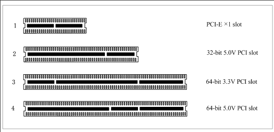
Figure 3 PCI and PCI-E slots
2.3 Clock Lines
If the user has only one card, then all the channels on this card run at the same clock frequency, at this point, no clock lines are needed. If the user installs multiple cards on a single machine at the same time, clock lines can provide many benefits at this point. If clock lines are not used, each analog card runs at its own clock frequency to send and receive data, and accuracy is compromised. During voice transmission, this problem is negligible, but in data transmission such as fax and modem, it may have an incalculable impact. Data loss will cause communication interruptions or even crashes. Clock lines allow all cards to operate under the same clock source, sending and receiving data at the same rate, without data loss.
If the user can find J914 (input) and J915 (output) interface on the card, it means the card supports clock line. Please refer to the link about the use of clock line HERE .
2.4 FXO, FXS modules
The FXO and FXS modules have the following simple differences.
- FXO-400 is a red module and FXS-400 is a green module, each module supports 4 analog signals.
- The FXO module corresponds to the FXO port, which is connected to a PSTN line and uses FXS signaling, while the FXS module corresponds to the FXS port, which is connected to an analog extension and uses FXO signaling.
2.5 Hardware Installation
- Turn off the power.
- Checking whether clock lines are required.
- Confirm that the slot type is PCI-E and insert the A810E/AE810E vertically into the slot.
- Connect the PSTN cable to the FXO port and the analog extension to the FXS port.
- Fix the board and ground it.
- Supply power.
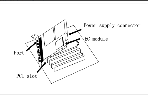
Figure 4 Hardware Installation
Note: An external power supply is required regardless of the type of module installed by the user. Static loops are essential during the above operation, and installation or removal of the board should only be done after power is removed. Please check the availability of the PSTN line and telephone before connecting the hardware. Once you are sure that the hardware is installed correctly, you can start the software installation.
Check to modify the interruption
Users can run the command “cat /proc/interrupts” to see if the A810E/AE810E has independent interrupts. If the A810E/AE810E shares interrupts with other devices, the board may not work properly. If needed, the A810E/AE810E allows users to modify interrupt pins during firmware upgrade to avoid interrupt conflicts.
2.6 EC Module Identification and Enabling
After completing the installation and configuration by referring to the corresponding board software installation manual, execute the command “dmesg | grep VPM” to check if the EC module is present
[root@localhost ~]# dmesg | grep VPM
OpenVox VPM: echo cancellation supports 32 channels
OpenVox VPM: echo cancellation for 32 channels
OpenVox VPM: hardware DTMF disabled.
OpenVox VPM: Present and operational servicing 1 span(s)
Follow the steps below to enable the EC module for echo cancellation.
Step 1: Set echocanceller=hwec as follows
#vim /etc/dahdi/system.conf
# Span 1: OPVXA24XX/24 “OpenVox A810 Board 25” (MASTER)
fxoks=1
echocanceller=hwec,1
fxoks=2
echocanceller=hwec,2
fxoks=3
echocanceller=hwec,3
fxoks=4
echocanceller=hwec,4
fxsks=5
echocanceller=hwec,5
fxsks=6
echocanceller=hwec,6
fxsks=7
echocanceller=hwec,7
fxsks=8
echocanceller=hwec,8
# Global data
loadzone = cn
defaultzone = cn
Step 2: Edit the file /etc/asterisk/chan_dahdi.conf and set the parameter echocancel=yes.
Step 3: Execute the command “dahdi_cfg -vvv”.
When there is a call in progress, execute the command “lsdahdi”, you will find that EC is enabled
[root@localhost ~]# lsdahdi
### Span 1: OPVXA24XX/24 “OpenVox A810 Board 25” (MASTER)
1 FXS FXOKS (In use) (EC: HWEC – INACTIVE)
2 FXS FXOKS (In use) (EC: HWEC – INACTIVE)
3 FXS FXOKS (In use) (EC: HWEC – INACTIVE)
4 FXS FXOKS (In use) (EC: HWEC – INACTIVE)
5 FXO FXSKS (In use) (EC: HWEC – ACTIVE)
6 FXO FXSKS (In use) (EC: HWEC – INACTIVE) RED
7 FXO FXSKS (In use) (EC: HWEC – INACTIVE) RED
8 FXO FXSKS (In use) (EC: HWEC – INACTIVE) RED
“EC: HWEC” means that EC is enabled. “ACTIVE” means that channel 5 has current calls
Chapter 3 Reference Table of Contents
Warm Tips.
If users encounter any problems during installation and use, please find answers and leave comments on OpenVox forum or wiki.
Appendix A Hardware Specifications
– Weight, Size
AE810E
Weight(g) : 85g (A810E) 10g (EC module)
Dimensions(mm): 136.3×111.2×16
AE810P
Weight(g) : 85g (A810P) 10g (EC module)
Dimension(mm): 136.3×106.7×16
– Interface
8 industry standard RJ11 interfaces
A810P PCI: 3.3V or 5V PCI 2.2 or higher
A810E PCI-E ×1, PCI-E ×2, PCI-E ×4, PCI-E ×8 or PCI-E ×16 slots
Power connector: 12V 4-pin connector
– Environment
Temperature: 0 ~50°C (working) – 40 ~125°C (storage)
Humidity: 10 ~ 90% non-condensing
– Power Consumption
Voltage: 3.3V/5V/12V, 3REN
Maximum power loss: 30.43W (2 FXS-400 modules)
7.83W (2 FXO-400 modules)
– Hardware and software configuration requirements
RAM 128 + MB
Linux kernel 2.4.X or 2.6.X
CPU 800+ MHZ
Appendix B RJ11 Pin Assignments
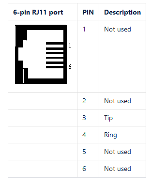
The A810P/E AE810P/E is compatible with both 4-pin and 6-pin RJ11 interfaces, and we illustrate the pin assignments in the following two tables.
4-pin RJ11
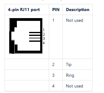
6-pin RJ11
