VoxStack Series Analog Gateway
1. Overview
What is VS-GW1600-40S?
OpenVox VoxStack Series Analog Gateway is an open source asterisk-based Analog VoIP Gateway solution for SMBs and SOHOs. With friendly GUI and unique modular design, users may easily setup their customized Gateway. Also secondary development can be completed through AMI (Asterisk Management Interface).
There are three models with VoxStack series Analog Gateway, the VS-GW1202-8S, VS-GW1202-16S and VS-GW1600-40S. There are 8 ports in VS-GW1202-8S. The Modular Design Analog Gateways are ranging from 8 up to 40 ports, developed for interconnecting the PSTN networks with a wide selection of codecs and signaling protocol, including G.711A, G.711U, G.729, G.722, G.723, ILBC and GSM to quickly reduce communication expenses and maximize cost-savings. With the unique design of the VoxStack gateway, it can support hot-swap. Users can simply add or remove the modules for hardware expansion or exchange.
The VoxStack gateway designs with 2 LAN switch boards to provide stack ability on the hardware upgrade. You can choose either of them.
The Analog gateway will be 100% compatible with Asterisk, Elastix, trixbox, 3CX, FreeSWITCH SIP server and VOS VoIP operating platform.
Sample Application
Figure 1-2-1 Topological Graph
Product Appearance
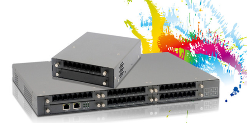
The picture below is appearance of Analog Series Gateway.
| Figure 1-3-1 Product Appearance |
VS-GW1202-8S VS-GW1600-40S
Main Features
- Modular and VoxStack design
- Based on AsteriskR
- Editable AsteriskRconfigurationfile
- Support T.38 fax relay and T.30 fax transparent, can continually fax multiple page
- Echo cancellation and Static jitter buffer
- Wide selection of codecs and signaling protocol
- DTMF relay
- Ring cadence and frequency setting
- MWI(Message waiting indicator)
- DHCP , DNS/DDNS, NAT Network
- VAG and CNG
- All hot-swap
- Stable performance, flexible dialing, friendly GUI
- Two-year time warranty
Physical Information
Table 1-5-1 Description of Physical Information
| Weight | 732g |
| Size | 15cm*19cm*4.5cm |
| Temperature | -20~70°C (Storage) |
| 0~40°C (Operation) | |
| Operation humidity | 10%~90% non-condensing |
| Power source | 12V DC/4A |
| Max power | 16W |
| LAN port | 2 |
Software
Default IP:172.16.99.1
User Name: admin
Password: admin
- Set the IP address of the computer so that it is on the same network segment as the IP address of the VoxStack series analog gateway device;
- Connect one of the LAN ports to the switch;
- Supply power, wait for a few seconds, and then check the status of the LED light;
- Enter the default IP in the browser and enter the web page of the device for configuration;
- For security reasons, change the default user name and password.
Figure 1-6-1 Login Interface

2. System
2.1 System Status
On the Status page, port information, SIP information, routing information, and network information are displayed.
Figure 2-1-1 System Status Display


2.2 Time Setting
Table 2-2-1 Time Setting Help Information
| Options | Description |
| System Time | Gateway system time. |
| Time Zone | The world time zone. Please select the same or closest time zone as your city. |
| POSIX TZ String | Posix time zone string. |
| NTP Server 1 | The time server domain name or host name. For example:[ time.asia.apple.com] |
| NTP Server 2 | The first standby NTP server. For example:[ time.windows.com] |
| NTP Server 3 | The second standby NTP server. For example:[ time.sina.gov] |
| Automatic synchronization from NTP server | Whether to enable automatic time synchronization from the NTP server. On, OFF. |
| Synchronize from NTP side | Synchronize time from NTP side. |
| Sync from client | Synchronize the time from the current machine. |
You can set the time synchronization as follows:
Fig. 2-2-1 Time Setting

2.3 Login Settings
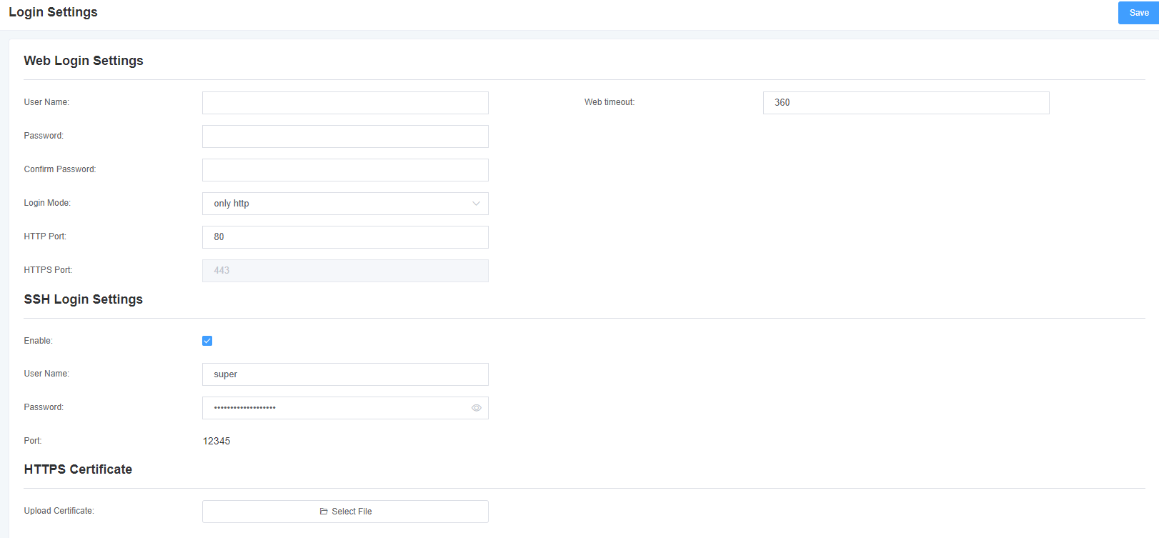
The gateway has no administrator role. Please reset the user name and password here to manage the gateway, which has all the permissions to manage the gateway. You can set the information about Web login and SSH login here. If you change the information here, you don’t need to exit, just re-enter the new user name and password.
Table 2-3-1 Login Settings Help
| Options | Description |
| User Name | The user name and password are defined here to manage the gateway, and this user has all the permissions that the gateway controls. Username: available characters “-_+.<>& 0-9a-zA-Z”. Length: 1-32 characters. |
| Password | Characters: available characters “-_+.<>& 0-9a-zA-Z”. Length: 4-32 characters. |
| Confirm Password | Please enter the same password again. |
| Login Mode | Select the mode of login |
| HTTP Port | specify the web service port |
| HTTPS Port |
Figure 2-3-1 Login Settings
2.4 General
On our gateway products, you can set different languages according to your needs. First, you need to turn on advanced mode, and then download the current language pack for the system. Finally, click the “Browse” option. After importing the language pack you need, the stand-alone “Add” button will take effect without restarting the gateway. You can enable the automatic restart function to restart your gateway after working for a certain period of time to achieve higher work efficiency. Figure 2-4-1 regular Interface

2.5 Tools
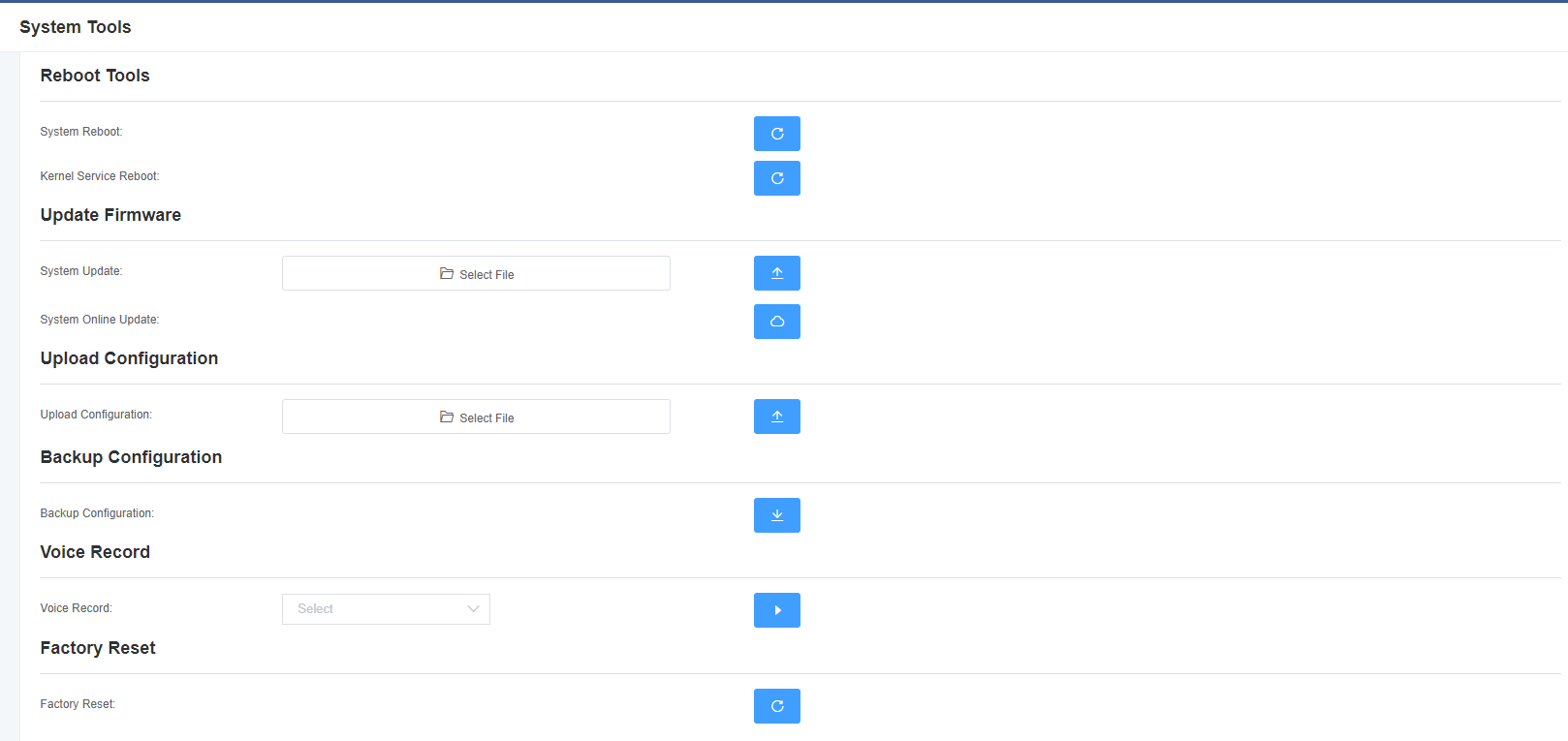
On the tool page, you can restart the gateway, upgrade the firmware, upload and backup configuration files, and restore factory settings. The analog gateway supports individual system restart, Asterisk restart, or file system switching.
Note: When you confirm the restart, the system will automatically end all current calls.
Table 2-5-1 Restart Help
| Options | Description |
| System Restart | This option will restart your gateway, cutting off all current sessions. |
| Asterisk restart | This option will restart the Asterisk, cutting off all current sessions. |
| Switch File System | The new version of the gateway retains two file systems. Click Switch File System to restart the system and switch to another file system. |
The analog gateway provides two firmware upgrade methods. You can choose to upgrade the system or upgrade the system online. Select the system upgrade, you need to download the relevant firmware from the OpenVox company website. System online upgrade operation is simple, for one-click upgrade.
After configuring your gateway, you can download the current configuration file. When you need to configure other gateways of the same model or restore the gateway to factory settings, you can upload the backup configuration file instead of reconfiguring the gateway. Note that the version of the configuration file and the current firmware version must be the same to take effect.
Select a module to record voice. The maximum recording duration is 3 minutes. When the recording time exceeds 3 minutes, the recording file will be downloaded automatically.
Note: You can call the dial-up mode to restore the gateway to factory settings. The phone is connected to the first FXS port of the gateway, dial “* 1*2*3*4” to restore the gateway to factory settings.
Figure 2-5-1 Tool Interface
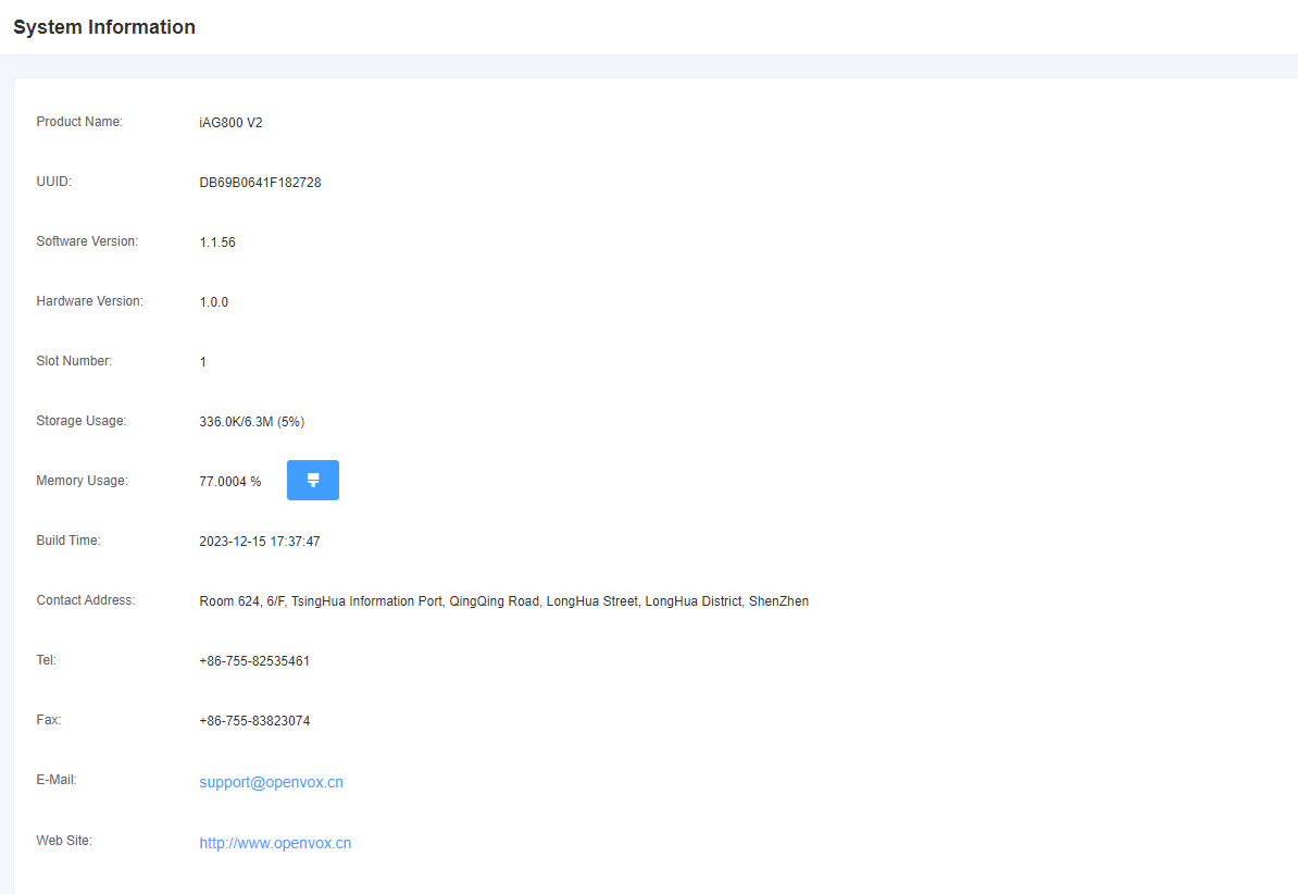
2.6 System Information
Figure 2-6-1 System Information Interface
3. Analog Settings
3.1 Channel Settings
Figure 3-1-1 Channel Status Display Interface

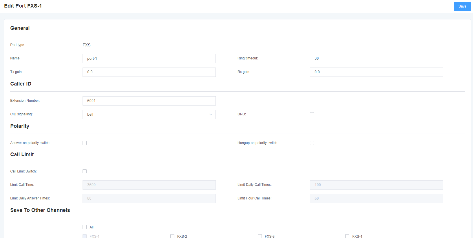
Click the Edit button to change the corresponding port information.
Figure 3-1-2 FXO port configuration
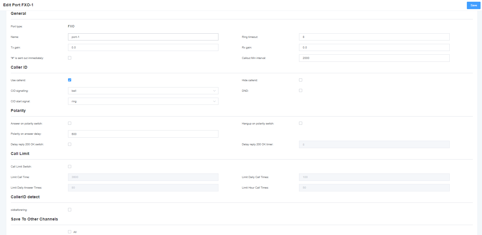
Figure 3-1-3 FXS port configuration
3.2 Dial Matching Table
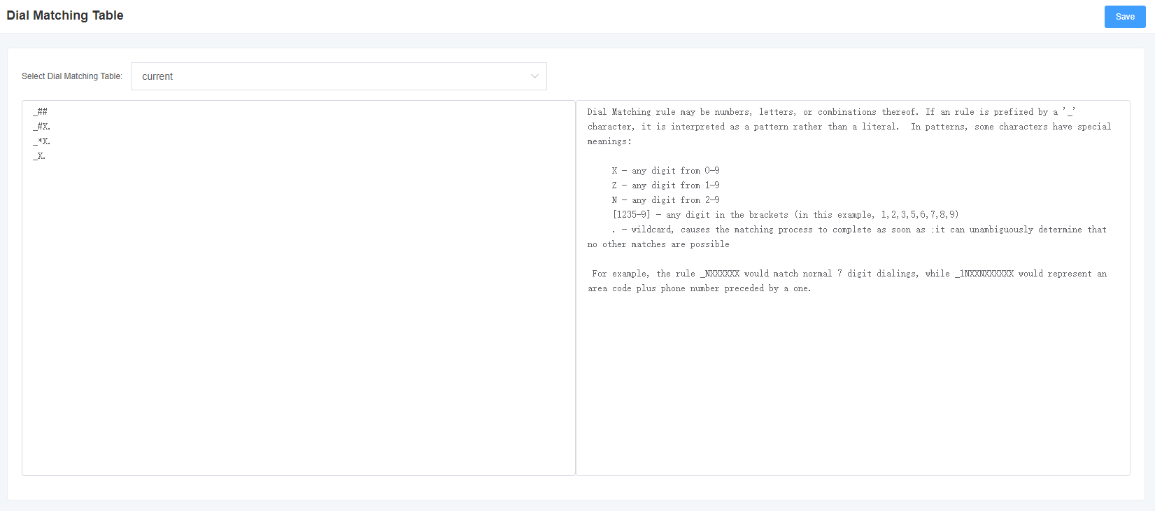
The dial matching table is used to effectively judge whether the received number is complete so as to send it out in time. Proper use of dial matching tables can help shorten the call setup time.
Figure 3-2-1 Dial Matching Table Interface
3.3 Advanced Settings
Figure 3-3-1 Global Settings
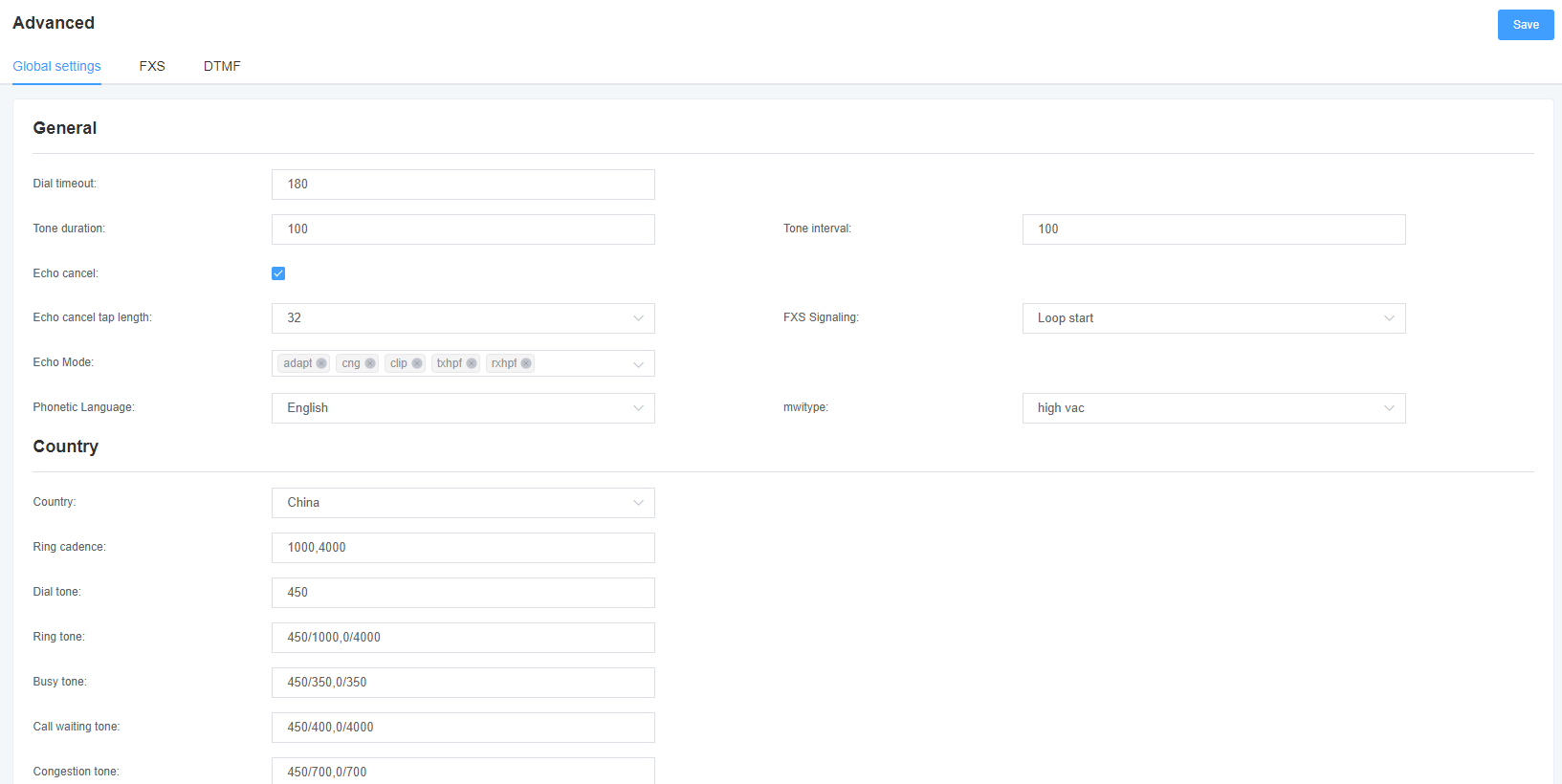
Table 3-3-1 Global Description
| Options | Description |
| Signal hold | The duration of the tone generated by the corresponding channel. (ms) |
| Call Gap | Tone playback interval (ms) |
| Call Timeout | Dial the specified timeout duration for a specific device. (seconds) |
| echo cancellation signal length | Hardware echo cancellation signal length. |
Table 3-3-2 Description of country settings
| Options | Description |
| National | Set the tone standard for the country where the gateway is located. |
| Ringing Rhythm | List of persistent rings. |
| Dial Tone | Set the off-hook dial tone. |
| ring back tone | Set the tone that is emitted to the caller when ringing. |
| busy tone | Set the tone when busy. |
| Call Waiting Tone | Set the background tone for incoming call waiting to play. |
| Congestion tone | Set the tone to play when congested. |
| Secondary Dial Tone | Set the prompt tone for double dialing after pressing the flash key. |
| Recording tone | Set the sound for the recording process. |
| Special message tone | Set a tone to play a special message (for example, the dialed number is not in the service area). |
Figure 3-3-2 FXO Table 3-3-3 FXO Description
| Options | Description |
| Busy tone detection | Used to detect a far-end hang-up or busy signal |
| Busy times | When busy tone detection is on, configure the number of busy tones the user hears before hanging up. |
| Busy Format Country | Select the country region to configure busy tone detection. |
Figure 3-3-3 FXS
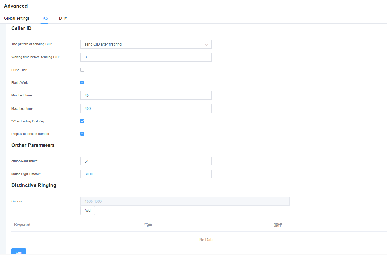
Table 3-3-4 Description of FXS
| Options | Description |
| Way to send CID | Some countries (such as the UK) have different ring tone systems, which means that the CID needs to be set later, not just after the first ring, which is after the first ring by default. |
| Length of time to wait before sending CID | How long (in milliseconds) we need to wait before sending the CID to the channel. |
| Send counter signal (DTMF only) | The counter signal is sent before the CID is sent to the channel. |
| Start Code (DTMF only) | Start code. |
| Stop Code (DTMF only) | Stop code. |
| Flap fork/flash break | Turn on or off the fork/flash function. |
| Minimum fork duration | Minimum fork duration. (ms) |
| Maximum fork duration | Maximum fork duration. (ms) |
| ‘#’ as end dial | Turns the dial key on or off. |
| Off-hook anti-shake | The anti-jitter delay size when the gateway FXS port detects the off-hook signal. Setpoint From 8ms to 2048ms (multiples of 8) The default value is 32ms. |
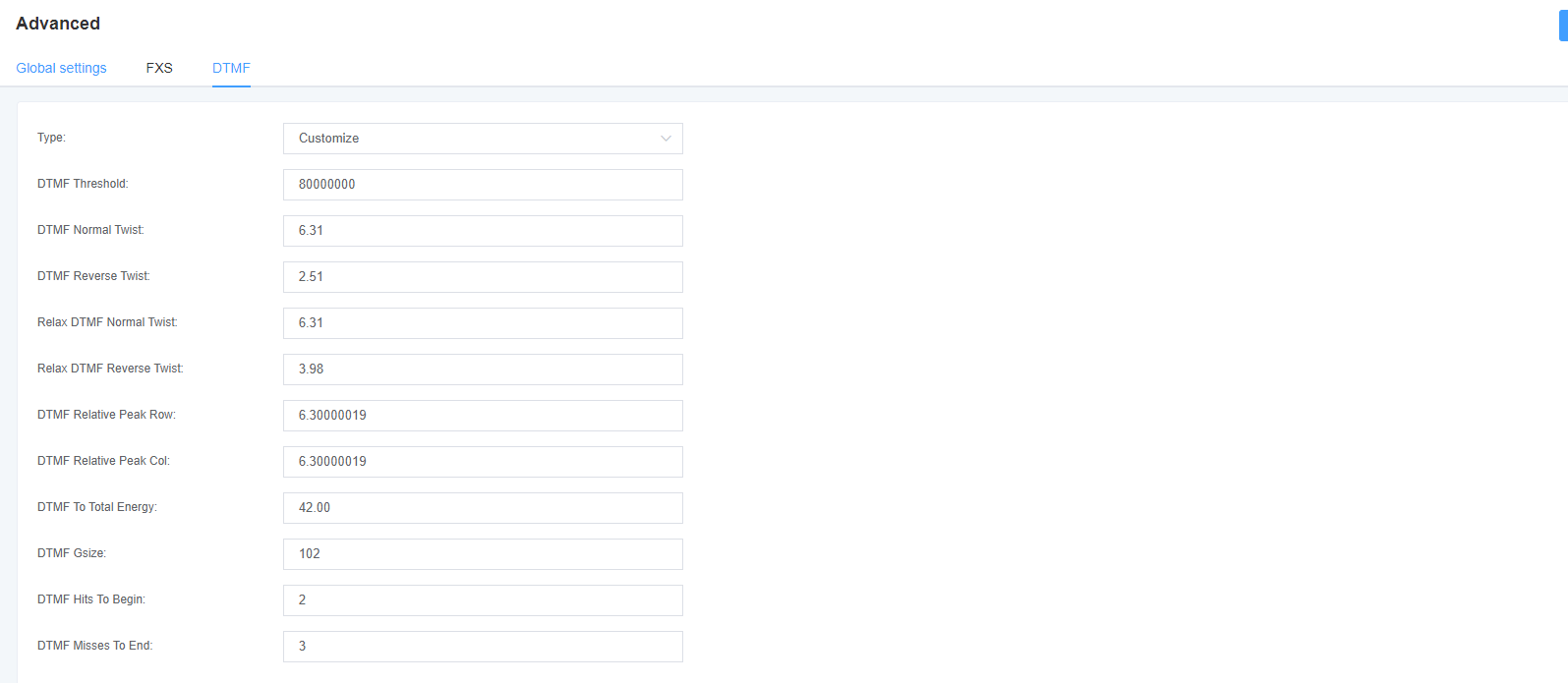
Figure 3-3-4 DTMF
3.4 Special Function Keys
Figure 3-4-1 Function keys
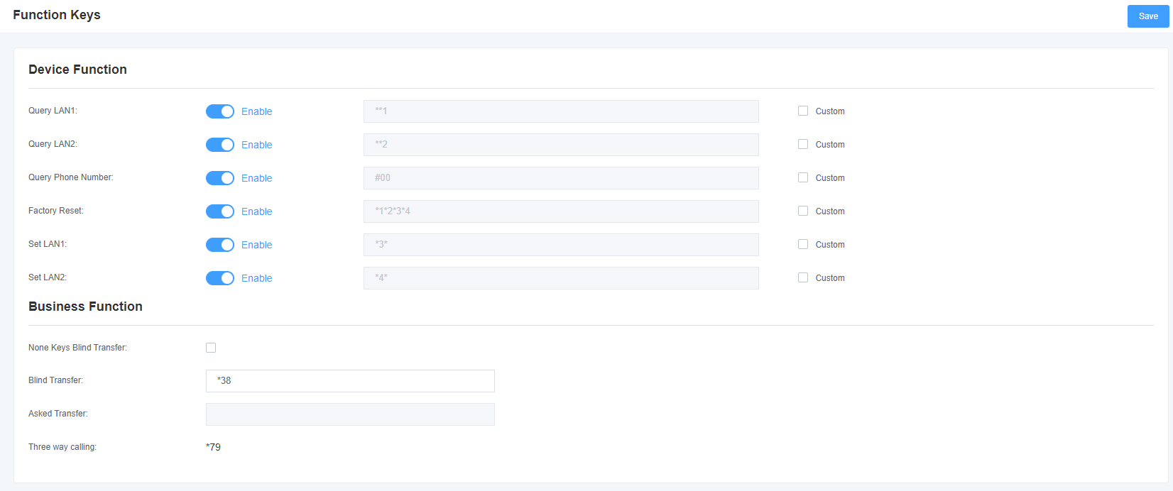
Table 3-4-1 Function Key Description
| Options | Description |
| Blind rotation without any key | Switch on: A talks to B, A forks dial * 38 (settable) and then dials the C number, C goes off-hook, A talks to C switch off: A talks to B, A forks dial * 38 (settable) and then dials the C number, A disconnects, C goes off-hook and B talks |
| blind rotation | Dialing rules configured before transferring calls after blind forwarding is turned on (default configuration * 38) |
| Inquiry Transfer | Dialing rules configured before transferring calls after the inquiry forwarding function is turned on (default configuration * 38) |
3.5 Drive
Fig. 3-5-1 Drive
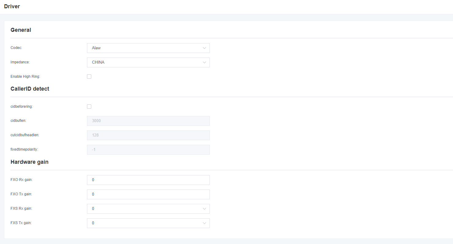
Table 3-5-1 Driver/regular Description
| Encoding | Global encoding settings: ulaw,alaw |
| Impedance | Impedance Settings |
| Non-standard CID detection | Adapt to the detection function switch different from the standard CID |
| CID media stream length | CID media stream length byte size |
| CID media stream header length | CID media stream header length byte size |
| Delay of sending polarity signal | Delay time of sending polarity line reversal signal |
| FXO to Terminal Gain | Set FXO to terminal gain, can fill value range: from -150 to 120 |
| FXO to IP Gain | Set FXO to IP gain, can fill the value range: from -150 to 120 |
| FXS to Terminal Gain | Set FXS to Terminal Gain, optional value:-35,0,35 |
| FXS to IP Gain | Set FXS to IP gain, optional value:-35,0,35 |
4. SIP Settings
4.1 SIP Endpoints
In this page, status information about the SIP account is displayed.
Figure 4-1-1 SIP Status

Click the Edit button to change the corresponding SIP information.
Figure 4-1-2 SIP Endpoints
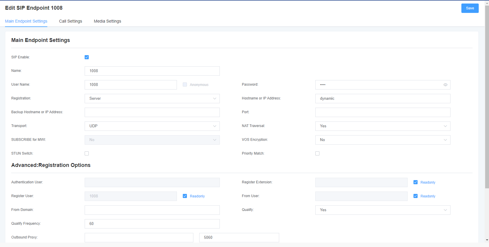
VoxStack series analog gateways provide three SIP registration methods: none, peer registration to the gateway, and gateway registration to the peer.
Table 4-1-1 Description of peer setting options
| Options | Description |
| Name | A relatively easy to understand name, the general situation can provide users with a reference. |
| User Name | The user name that the peer authenticates with the gateway. |
| Password | The password for authentication between the peer and the gateway, allowing the use of letters. |
| Register | No-anonymous registration; The opposite end is registered to the gateway-the gateway is used as a server, and the SIP opposite end is registered to the gateway; The gateway is registered to the opposite end-the gateway is used as a client, and SIP terminals need to be registered to the server; |
| Domain name or IP address | The IP address or domain name of the peer or dynamic (if the peer is a dynamic domain name). These require registration. Note: If you enter a domain name and change the DNS, you must restart the Asterisk. |
| Transmission mode | Set the possible transmission types for outgoing, using the order. When you use various transport protocols, UDP,TCP,TLS. The first enabled transport type is only used for outgoing messages until registration occurs. If the peer requires another transmission type during registration, the transmission type may be changed to another 1 transmission type. |
| NAT Traversal | Problems with NAT addresses during incoming SIP or media sessions. |
Table 4-1-2 Registration Option Description
| Options | Description |
| Authenticated User | Just a username used at the time of registration. |
| Registered extension | When the gateway registers with the SIP proxy as a SIP user agent, the call is forwarded to this extension. |
| Registered User Name | The registered user name is the user in the register => user[:secret[:authuser]]@ host[:port][/extension]. |
| User Source | The user name used to identify the gateway peer. |
| Domain name from | Used to identify the domain name of the gateway peer. |
| Port | The port number used by the gateway to link the peer. |
| Authentication | Whether to check and peer link status. |
| Detection frequency | Check the link status of the peer and peer end every few seconds. |
| External Agent | The gateway will send signaling to this foreign agent instead of directly to the peer. |
| custom registration switch: | After opening, customers can customize the registry themselves. |
| enable outboundproxy to replace host |
Figure 4-1-3
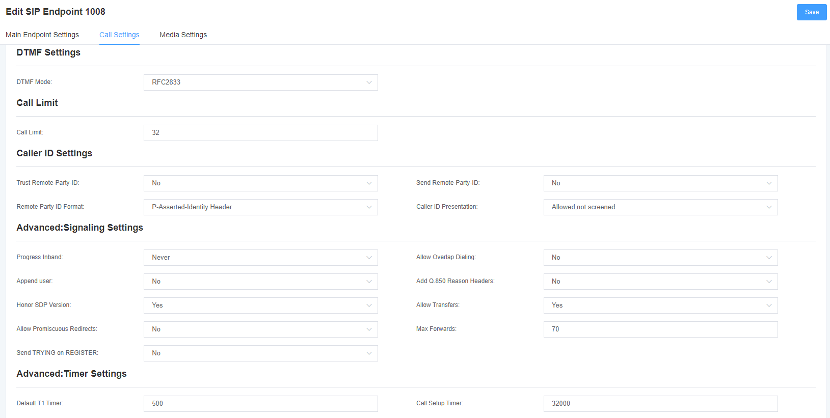
Table 4-1-3 Call Setup Options Help Information
| Options | Description |
| DTMF mode | Set the default mode for sending STMF. Default: rfc2833. Other options: ‘info’, SIP INFO message (application/dtmf-relay); ‘Inband’, Inband audio (requires 64kbit codec-alaw, ulaw). |
| Call barring | Set a call limit to the maximum number of calls that can be allowed at the same time. |
| Trust Remote-Party-ID | Whether the Remote-Party-ID header is trusted. |
| Send Remote-Party-ID | Whether to send the Remote-Party-ID header. |
| peer party id format | How to set the Remote-Party-ID header: from Remote-Party-ID or from P-Asserted-Identity. |
| Calling ID Description | Whether to display caller ID. |
Figure 4-1-4 Media Settings
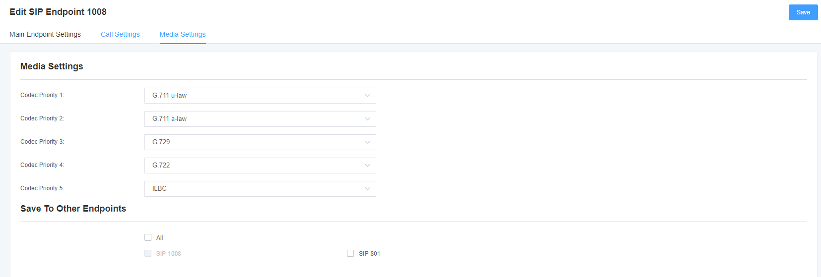
Table 4-1-4 Media Settings Help
| Options | Description |
| Media Settings | Select the encoding type from the drop-down list, and select different encoding methods for different encoding priorities. |
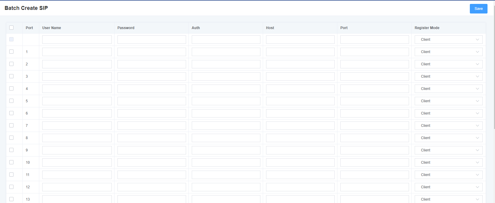
4.2 Batch Creation of SIP accounts
On this interface, the user can create multiple SIP accounts at once. You can choose any registration mode.
Figure 4-2-1 Adding SIP accounts in batches
4.3 SIP Advanced Settings
4.3.1 Network
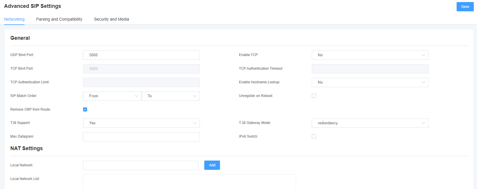

Table 4-3-1 Network Selection
| Options | Description |
| UDP binding port | Select a port that listens for UDP streams. |
| enable TCP | Enables the TCP link request service (not enabled by default). |
| TCP Bind Port | Select a port that listens for TCP streams. |
| TCP Authentication Timeout | Maximum number of seconds for client link validation. If the client is not authenticated before the time expires, the client will be disconnected. (Default: 30 seconds) |
| TCP Authentication Restrictions | The maximum number of simultaneous links allowed in a given time. (Default: 50 seconds) |
| Enable hostname lookup | Turn on DNS SRV lookup for outbound calls. Note: The gateway is only the first host in the SRV record, this feature can be used in dial activation in the form of dialing through the domain name to SIP phones on the Internet. |
4.3.1.1 NAT Settings
Table 4-3-2 NAT Settings
| Options | Description |
| Local Network | Format: 192.168.0.0/255.255.0.0 or 172.16.0.0/12. A list of IP addresses or IP ranges within the NAT’s network. When NAT exists between the gateway and the peer device, the gateway will replace the IP address in the SIP and SDP messages with an extended IP address. |
| Local Network List | Added the list of local IP addresses. |
| Subscription Network Change Time | When the external network address changes, the gateway can detect the change by using the test_stun_monitor module. When the stun_monitor is installed and configured, the chan_sip will update all outgoing registrations when the monitor detects any form of network change. This option is enabled by default, but the res_stun_monitor can only take effect once. If res_stun_monitor is enabled and you do not want changes on the network to generate outbound registrations, use the options below to disable this feature. |
| Local Match External Address | If the match is successful, only the external address or domain name is replaced. |
| Dynamic and static selection | Dynamic hosts are not allowed to register with the IP address of the static host. This will avoid the error of registering with the same IP. |
| External TCP Port Mapping | When the gateway is behind a static NAT or PAT, the TCP port is mapped externally. |
| External IP Address | NAT external IP address (and optional TCP port) External IP address = hostname [: port number] This format defines a fixed address for SIP and SDP information transmission. For example: external IP address = 12.34.56.78 external IP address = 12.34.56.78:9900 |
| External Host Name | External hostname (and optional TCP port) for NAT |
| Host Name Refresh Interval | How often to perform a hostname lookup. You can also configure a domain name. The gateway will perform a DNS query. This method is not recommend. Try to use IP and configure externip. |
4.3.1.2 RTP Settings
Table 4-3-3 RTP Settings
| Options | Description |
| Starting RTP Port | Start range for RTP port numbers. |
| End RTP port number | End range for RTP port numbers. |
| RTP Timeout | The RTP timeout time. |
4.4.2 Parsing and Compatibility
Figure 4-4-2 Parsing and Compatibility
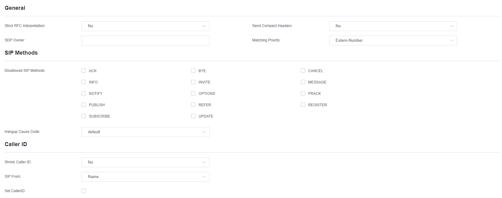
 Table 4-4-4 Parsing and Compatibility Settings Help
| Options | Description |
| Strict RFC parsing | Open the tag value detection in the message, URls and multi-line formatting header information Chinese standard character conversion and other strict SIP compatibility issues (default is yes). |
| Send compact head | Sends a compact SIP message header. |
| SDP Owner | Allows you to change the domain of the SDP username©. This field cannot contain spaces. |
| SIP method not allowed | When talking back to other SIP peers, then the other peers should include an Allow header to tell us the implementation of the SIP method. However, some peers do not include the Allow header or fake the methods they implement. In such a case, the gateway will assume that the peer supports all known SIP methods. If you know that your SIP peer does not provide support for a particular method, then you may want to provide a list of methods that the peer does not implement disallowed_methods. Note: If your opposite end is real, then there is no need to set this item. |
| Shrink caller ID | This function can remove ‘(‘, ”, ‘)’, non-trailing ‘, ‘, and ‘_’ not in square brackets. For example, when this option is enabled, the value of caller ID changes from 555.5555 to 5555555. The default is enabled. |
| Maximum Registration Timeout | The maximum time allowed for incoming registration and subscription, in seconds. |
| Minimum Registration Timeout | The minimum length of registration and subscription, the default is 60. |
| Default Registration Timeout | The default inbound and outbound registration length. |
| Registration Timeout | How long does it take to re-register an extension? The default is 20 seconds. |
| Number of Registration Attempts | The number of registration attempts before abandoning registration. |
4.4.3 Security and Media
Figure 4-4-3 Security and Media
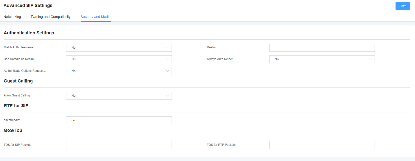
Table 4-4-5 Security Setting Help
| Options | Description |
| Match Authentication User Name | If available, use the username field of the authentication line to match the username instead of using the username field. |
| Domain | For certified realms, all domains must remain globally unique according to RFC3261 criteria. Generally, it can be set to host name or domain name. |
| Use a domain name as a domain | Use the SIP domain as the boundary for the domain. |
| Maintain Validation Decisive | When an INVITE or REGISTER request is rejected for any reason, the same reason is always used, the user name is valid but the password is incorrect. It will not tell the requester whether there is this user or peer, which will reduce the possibility of attackers scanning SIP accounts. This parameter is enabled by default. |
| Verify OPTIONS request | Turning this parameter on will cause the OPTIONS request to take effect just like an INVITE request. This parameter is turned off by default. |
| Allow customer calls | Allow or deny client calls (on by default, allow). If your gateway is connected to an external network and allows customers to call, you want to check what services are available to everyone and turn on in the default context. |
Table 4-4-6 Media Settings
| Options | Description |
| Early Media | Some SDN connections send empty media frames or process state before the phone rings. The SIP tunnel will send 183 representation as early null media. The user therefore receives no ringing signal. Set this to “yes” to organize additional media before receiving the call process (the SIP tunnel will not send the 183 session process for other early media). The default is ‘yes ‘. Confirm that the configuration file of SIP peer is set to progressinband = never. In order to’ no answer’ function be applied, you need to execute progress() before running app. |
| TOS for SIP packets | Sets the service type for SIP packets. |
| TOS for RTP packets | Set the service type for RTP packets. |
4.5 Sip Account Security
The mock gateway supports TLS protocol encryption. It can work in TLS server mode, generate the session key used in the secure connection process, or register as a client and upload the key file provided by the server.
Figure 4-5-1 TLS Settings
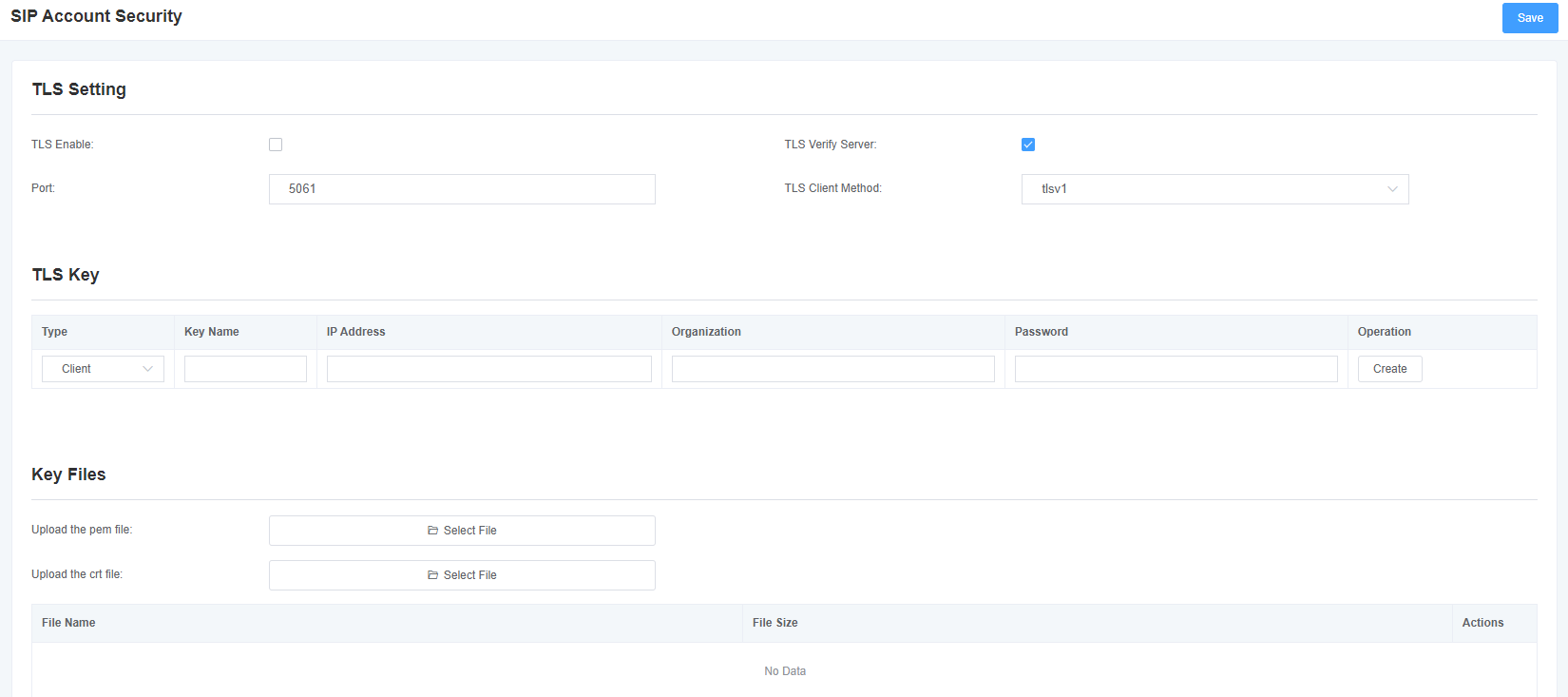
Table 4-5-1 TLS settings
| Options | Description |
| Open | Turn TLS on or off |
| TLS Authentication Service | Turn the TLS authentication service feature on or off (off by default) |
| Port | Specify a port for a remote connection |
| TLS Client Mode | Specifies the Outbound client connection protocol. The mode includes: tlsv1, sslv3, and sslv2. The default is sslv2. |
5. Routing Settings
The gateway has a user-friendly interface and is very flexible to set up. It supports up to 512 routing rules and each routing rule supports up to 100 primary/called number filtering and conversion operations. It supports DID function (DID function usage: How to use DID function with China Telecom’s T1/E1 gateway). The gateway supports relay group and relay priority management.
5.1 Call Routing Rules
Call routing rules can be created here.
Figure 5-1-1 Call routing rule settings
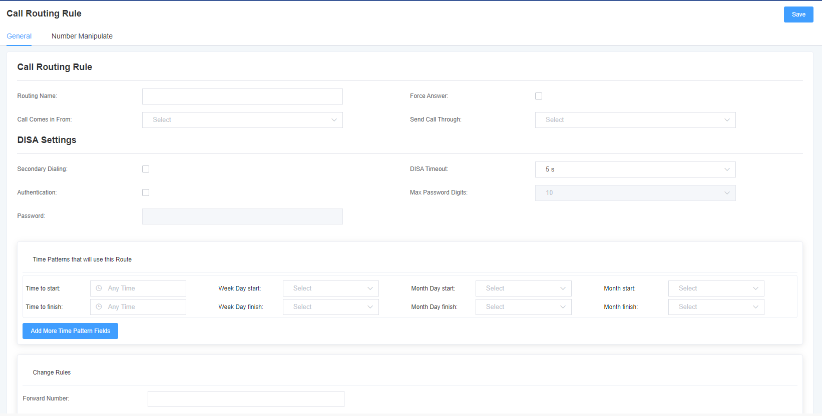

Table 5-1-1 Description of routing rules
| Options | Description |
| Route Name | It’s a regular name. Usually used to describe the type of match (for example, ‘sip1 TO port1’ or ‘port1 TO sip1’). |
| Call from | The source of the call. |
| Call Delivery | The delivery destination for incoming calls. |
| Time patterns using this rule | The time mode setting of the routing rule. |
| Forward Number | Do you want to forward the call to the number? This is very useful when you have a call forwarding. |
| Call Failure Handling | The gateway will try to send the call in the order you specify. |
Figure 5-1-3 Number Transformation
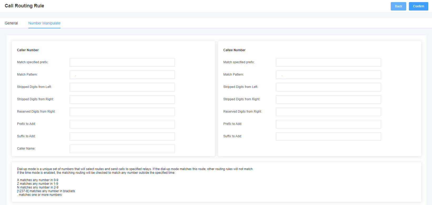
Table 5-1-2 Advanced routing rules
| Options | Description |
| Calling/called number filtering and transformation | The dial pattern is 1 unique set of digits that will route and send the call to the designated trunk. If the dialing pattern matches this route, the other routing rules will not match. If the time mode is enabled, then the matching route will be checked to see if it matches any number in 0-9, z in 1-9, n in 1-9, any number in 2-9 [1237-9], matches any number in brackets <e.g. 1,2,3,7,8,9> * matches one or more number Prepend <prefix>: the number to add if the pattern match succeeds. If the dialed number matches the pattern specified in the subsequent column, the number is added before being sent to the relay. Prefix <prefix>: removed when the pattern matches successfully. The dialed number is matched against the pattern specified in the subsequent columns, and once a match is successful, the prefix is removed from the number before it is sent to the relay. Match Pattern <matching pattern>: The dialed numbers are compared GG1 the ‘prefix + the number of this matching pattern. Once the match is successful, the matching pattern portion of the dial is sent to the relay. SDfR <number of digits deleted from the right>: number of digits deleted from the right. If this value exceeds the length of the current number, the entire number will be deleted. RDfR <number of reserved digits from right>: number of reserved digits from right. StA <add suffix>: This number is added from the right end of the current number. Caller Name <caller display name>: set the caller name you like before sending this call to the terminal, allowing the use of local languages, such as Chinese and Latin. |
5.2 Group
Sometimes you want to make a call from a certain port, but you don’t know if it is available, so you also have to check which port is available. This will be troublesome. But with our products, you no longer need to worry about this problem. You can add multiple ports or SIPs to a group. When you want to make a call, it will automatically look for available ports.
Figure 5-2-1 Group Rules

Table 5-2-1 Routing group description
| Options | Description |
| Group Description | The name of the route, which describes the type of call route, such as sip1TOport1 or port1TOsip2. |
5.3 Bulk Creation of Call Routing Rules
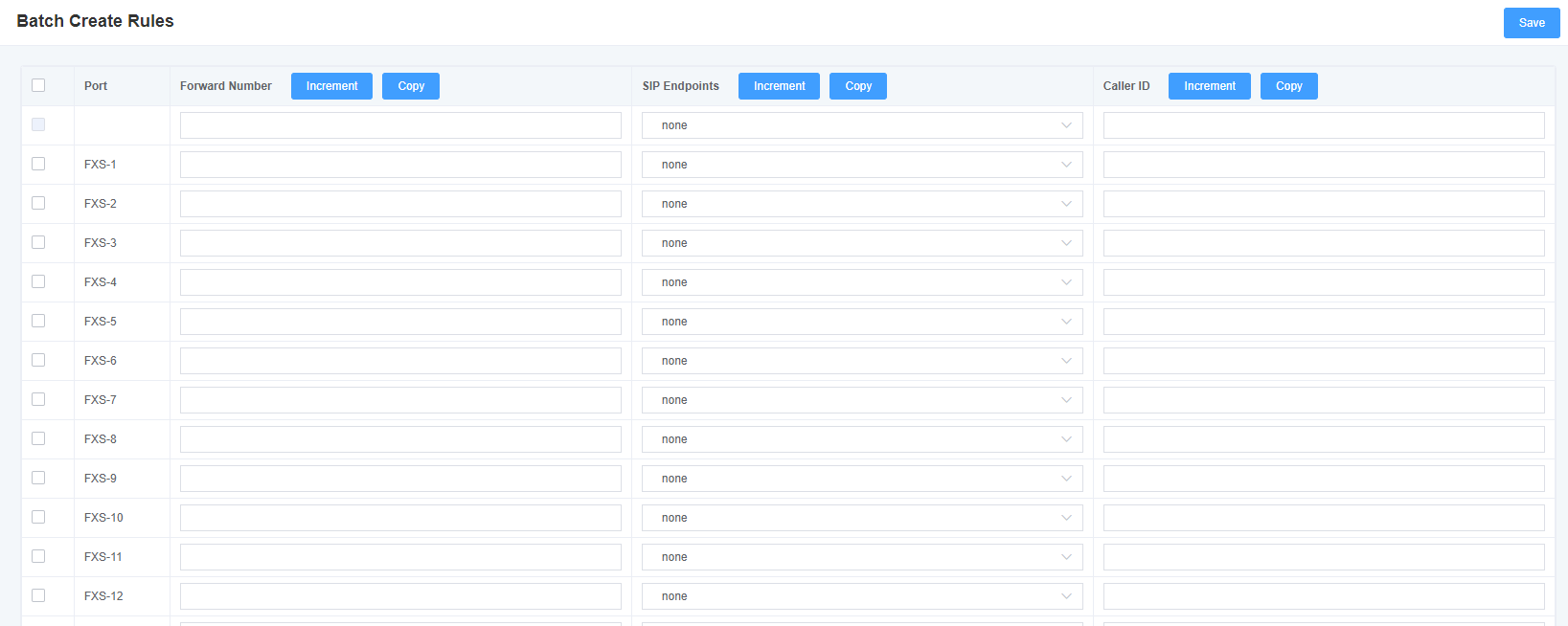
If you have phones bound on each FXO port and want to establish a separate call route for each of them. For your convenience, you can create routing rules for each FXO port in bulk on this page.
Figure 5-3-1 Creating Call Routing Rules in Bulk
5.4 Advanced Settings
In the default mode, FXS and SIP are 1 bound. After FXS port opens flexible routing, it is compatible with the original sip extension binding, and SIP account binding is no longer required, and relevant routing rules can be set. In this case, you can choose to turn on the FXS or SIP internal call function.
Figure 5-4-1 Advanced Settings


6. Network Configuration
6.1 Network Configuration
There are three LAN IP types to choose from: Factory, Static, and Dynamic Host Configuration. The default type is factory, and the default IP address is 172.16.99.1. If you forget the current IP, you can connect the phone to the first FXS port of the analog gateway and dial “** “to query the current IP.
Figure 6-1-1 LAN configuration interface
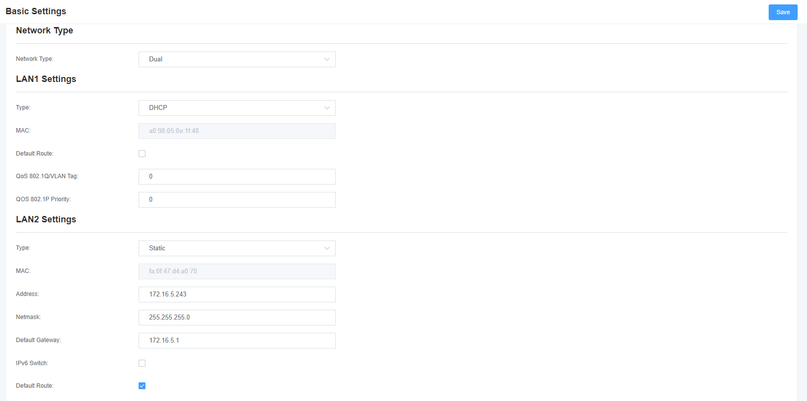
Table 6-1-1 Network Settings Description
| Options | Description |
| Interface | The network interface name. |
| Type | Method to get the IP. Factory: Obtain IP address through slot number (check slot number under system-> information directory). Static: Manually set the gateway IP address. Dynamic host configuration: dynamically obtains the gateway IP address. |
| Physical Address | The physical address of the network interface. |
| Address | The gateway IP address. |
| Subnet Mask | Gateway subnet source code. |
| Default Gateway | The default gateway IP address. |
| Domain Name Server | List of domain name server IP addresses. This information is obtained primarily from the local network service provider. |
| Open | Enable or disable the reserved IP address switch. On, OFF. |
| Reserved address | The gateway reserved IP address. |
| Reserved Subnet Mask | The subnet mask corresponding to the reserved IP address. |
6.2 VPN Settings
You can select the VPN type and upload the OpenVPN client configuration file or fill in the account information of the PPTP VPN. If successful, you can see a VPN virtual network card on the system status page. You can refer to the prompt and sample configuration of the parameter.
Figure 6-2-1 VPN interface

6.3 DDNS Settings
You can enable or disable DDNS (Dynamic Domain Name Server) as needed.
Figure 6-3-1 DDNS interface

Table 6-3-1 DDNS option description
| Options | Description |
| Dynamic Domain Name | Enable/Disable dynamic domain names (dynamic nameservers). |
| Type | Set the dynamic domain name server type. |
| User Name | Name of the domain name server login account. |
| Password | Dynamic domain name server account password. |
| Domain | The domain to which the web server belongs. |
6.4 tools
This tool is used to detect network connections and can perform Ping commands on the Web interface.
Figure 6-4-1 Network detection
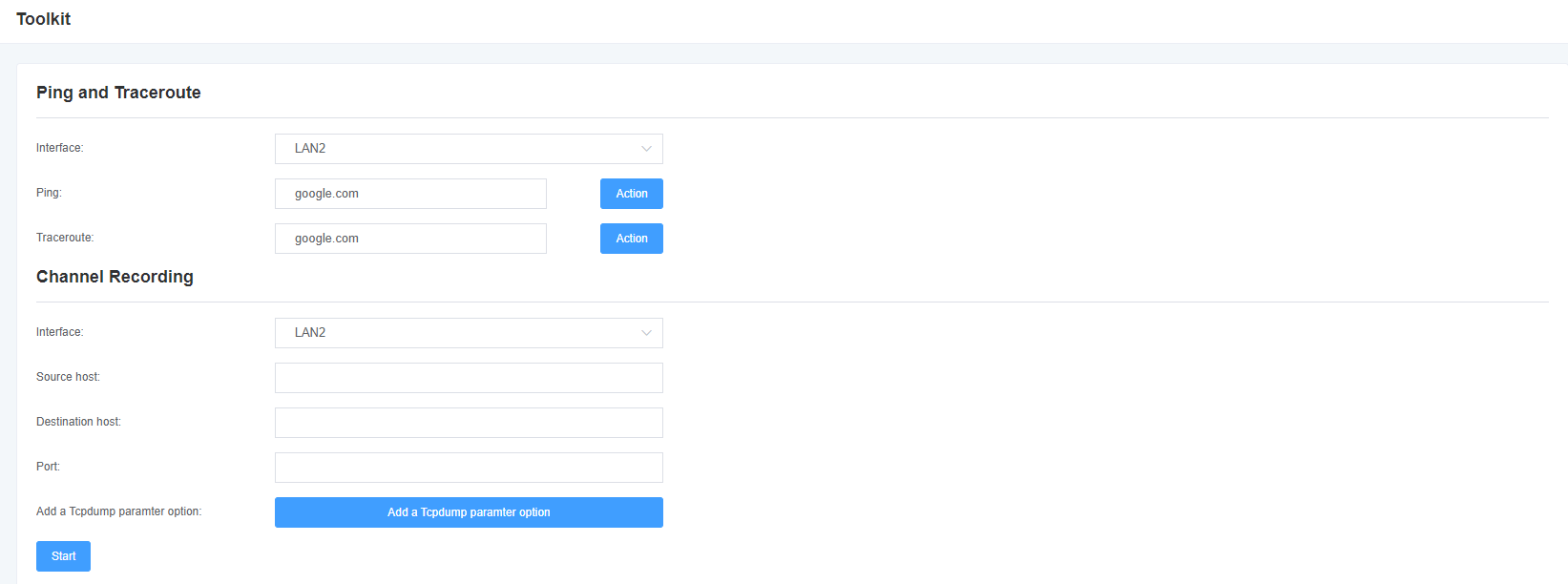
Table 6-4-1 Channel Record Description
| Options | Description |
| Interface | The network interface name. |
| Source Host Address | Specify the source address of the data you want to get. |
| destination host address | Specify the destination address where you want to get the data. |
| Port | Specify the port where you want to get the data. |
| Channel | Specify the number of the channel you want to get the data from. |
| Tcpdump using option parameters | tcpdump crawl network data according to the specified parameters. |
6.5 Security Settings
Figure 6-5-1 Firewall Settings
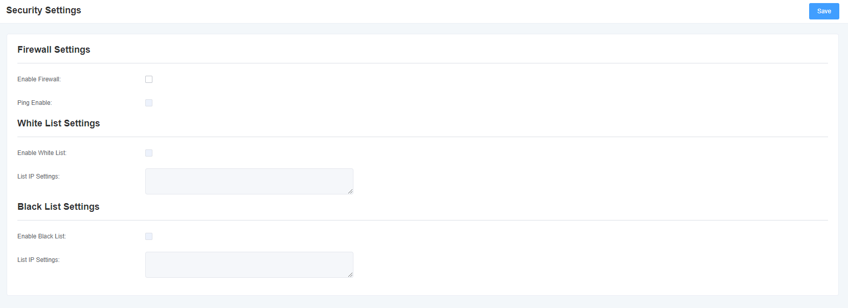
Table 6-5-1 Firewall Setting Instructions
| Options | Definition |
| Enable Firewall | If you use black/white lists and security rules, you need to enable this option. |
| Enable Ping | Whether to enable the ping function. If the status is OFF: disable ping, the gateway does not allow ping. |
Table 6-5-2 White/Black List Description
| Options | Definition |
| White/Black List Switch | Whether to enable the white/black list. |
| IP List | IPs are separated only by a comma. |
6.6 Firewall Security Rules
Figure 6-6-1 Security rule settings

Click the Save button to submit and apply the configuration.
6.7 Static Routing Settings
In the Static Route page, the network interface, destination IP address, subnet mask, via gateway, hop count, and action for the static route are displayed. Static routes can be added here. Click the Add button to add a static route.
Figure 6-7-1 Static route setting interface

7 Advanced Options
7.1 Application Program Interface
This page is not available until this feature is turned on.
Figure 7-1-1 API interface
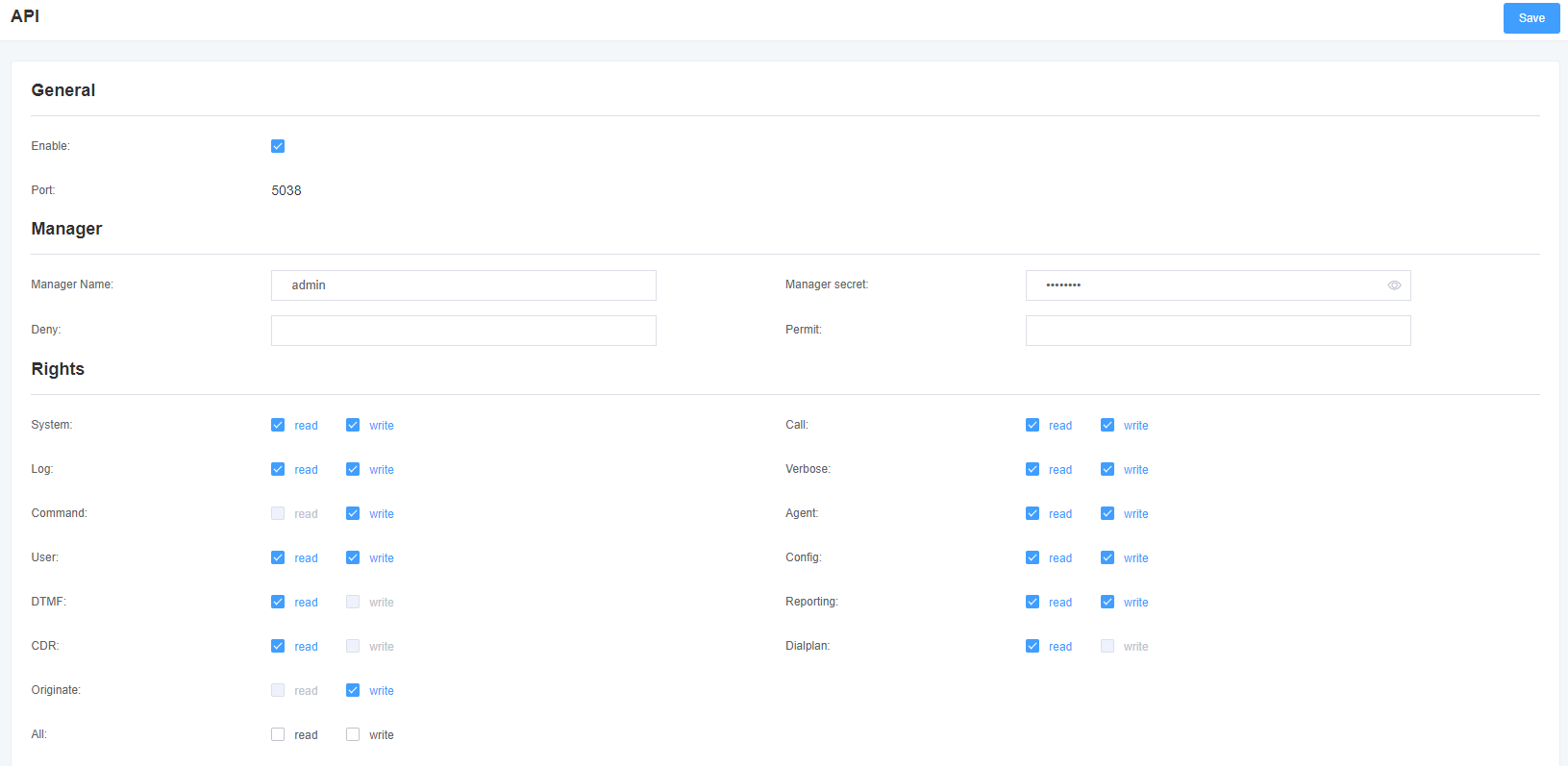
Table 7-1-1 Asterisk API
| Options | Description |
| Port | The network port number. |
| Administrator Name | The administrator name cannot contain spaces. |
| Administrator Password | The administrator password. String: available characters “-_+.<>& 0-9a-zA-Z”. Length: 4-32 characters. |
| Reject | If you want to deny access to certain networks or hosts, use the & symbol as the delimiter. For example: 0.0.0.0/0.0.0.0 or 192.168.1.0/255.255.255.0 & 10.0.0.0/255.0.0.0. |
| Permitted | If you want to allow some network or host access, use the & symbol as a delimiter. For example: 0.0.0.0/0.0.0.0 or 192.168.1.0/255.255.255.0 & 10.0.0.0/255.0.0.0. |
| System Log | Basic system information and common system management commands, such as shutdown, restart, and reload. |
| Call | Channel information and setting information of channels in use. |
| Log | Log information. Read only. (Defined but not used) |
| Details | Debugging information. Read only. (Defined but not used) |
| Command | CLI commands allowed to run. Read only. |
| Agent | Queue and agent information and the ability to add queue members to the queue. |
| User | Allows sending and receiving user events. |
| Configuration | Ability to read and write configuration files. |
| DTMF | Receive DTMF. Read only. |
| Report | The ability to obtain system information. |
| Call recording | cdr_manager output if loaded. Read only. |
| Dial Plan | Receives NewExten and VarSet events. Read only. |
| Initiate | Allow new calls to be initiated. Read only. |
| Select All | Select All or Deselect All. |
7.2 Command Line Interface
Figure 7-2-1 Command Line Interface

7.3 File Editing
Figure 7-3-1 Configuration File List
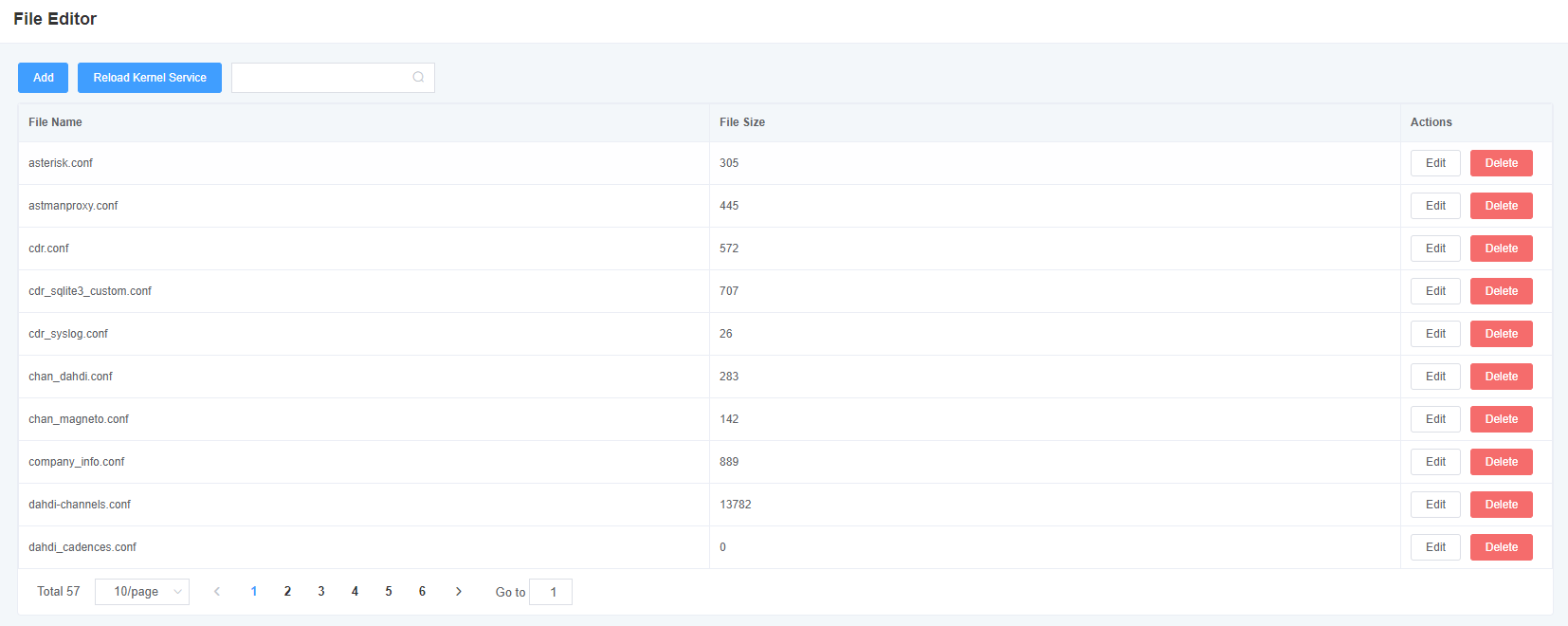
Note: After modifying the configuration file, you need to reload the Asterisk.
7.4 Cloud Management
Figure 7-4-1 Cloud management interface

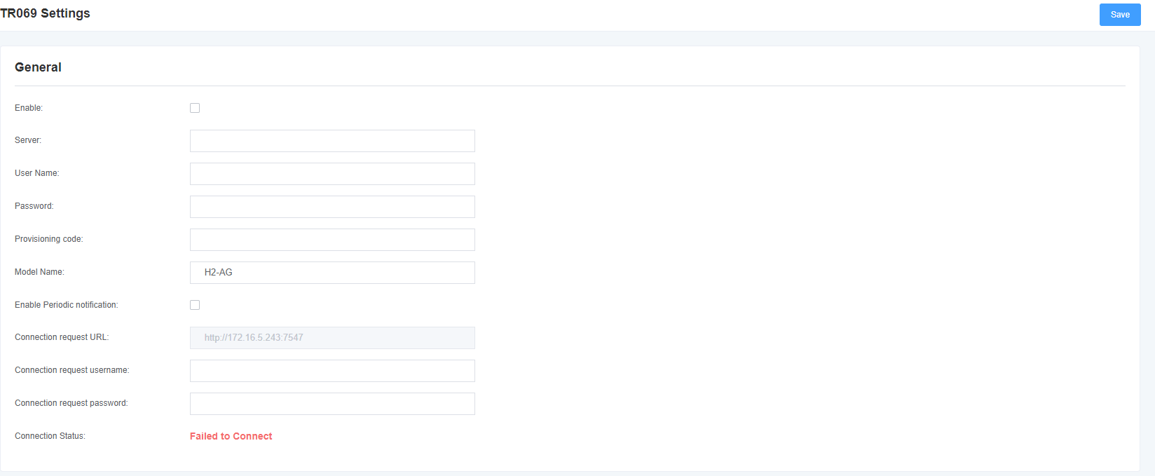
7.5 TR069
Figure 7-5-1 TR069 Interface
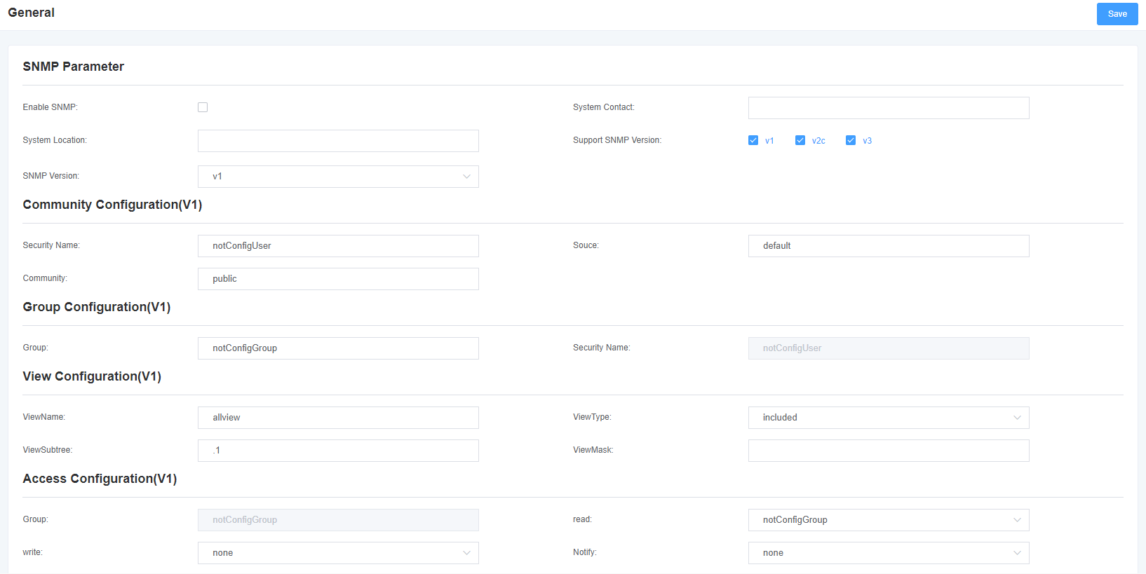
7.6 SNMP
Figure 7-6-1 SNMP interface
7.7 Automatic Configuration
Figure 7-7-1 Automatic configuration interface

8 System Log
8.1 Log Settings
On the Log Settings page, open the corresponding log options to view different logs in the corresponding interface. For example, after turning on the system log, you can go to the system log to view the records, otherwise, the system log has no content output. The other log pages are the same.
Figure 8-1-1 Log Settings
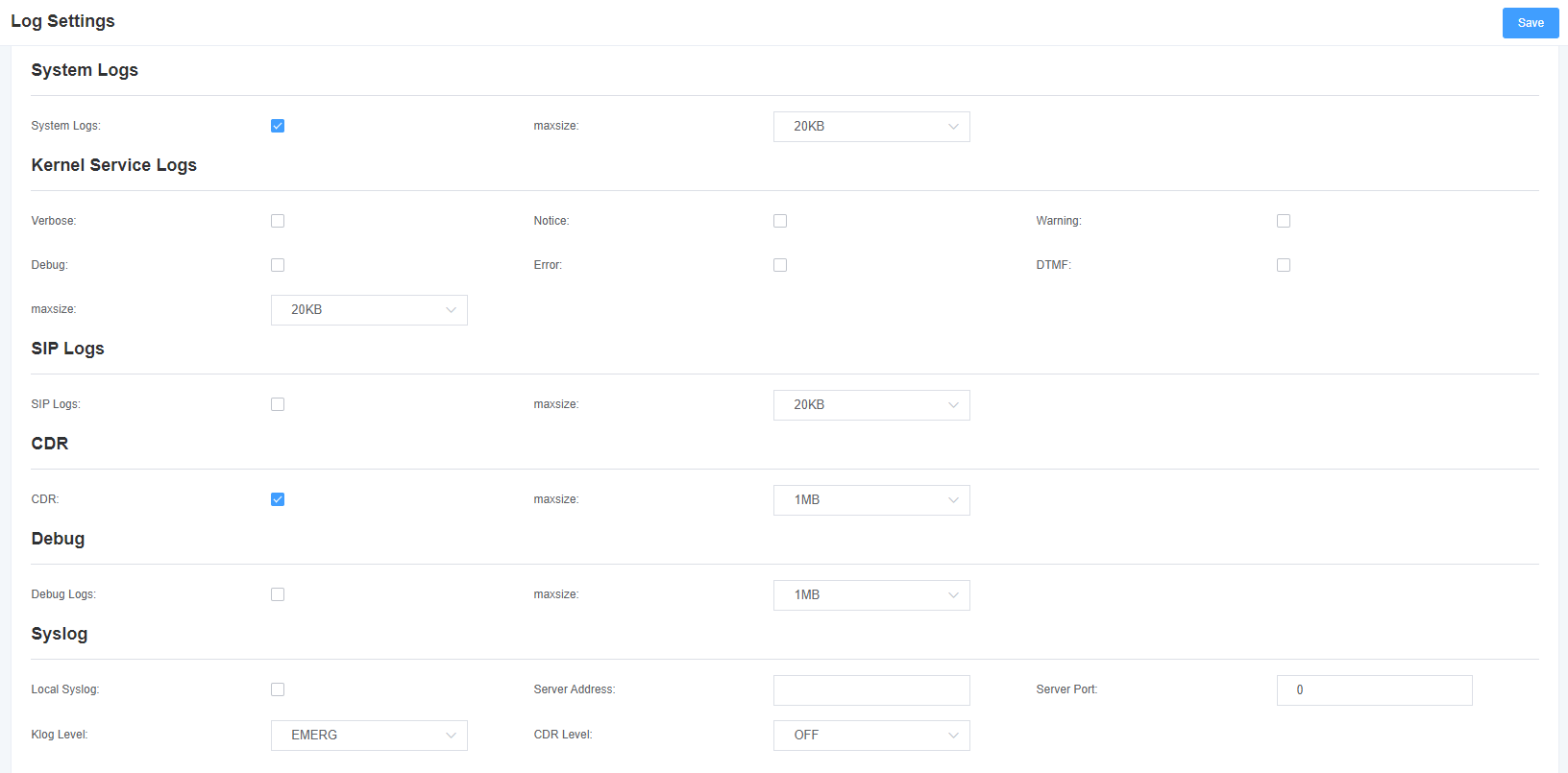
Table 8-1-1 Description of log options
| Options | Description |
| System Log | Whether to open the system log. |
| Auto Clear (System Log) | Select Open: When the log information reaches the set maximum value, the system will delete half of the files and write new logs into it. Select Close: The log will be retained and will continue to grow. By default, the default size is 1MB. |
| Details | Asterisk console information. |
| Attention | Asterisk the attention information of the console. |
| Alarm | Asterisk the alarm message on the console. |
| Debugging Information | Asterisk console debugging information. |
| Error | Asterisk console error messages. |
| DTMF | Asterisk console DTMF messages. |
| Automatic purge (Asterisk log) | Select Open: When the log information reaches the set maximum value, the system will delete half of the files and write new logs into it. Select Close: The log will be retained and will continue to grow. The default size is 100KB. |
| SIP Log | Whether to enable SIP log. |
| Automatic Purge (SIP Log) | Select Open: When the log information reaches the set maximum value, the system will delete half of the files and write new logs into it. Select Close: The log will remain and continue to grow. The default size is 100KB. |
| DAHDI Log | Whether to enable DAHDI log. |
| Automatic Purge (DAHDI Log) | Select Open: When the log information reaches the set maximum value, the system will delete half of the files and write new logs into it. Select Close: The log will be retained and will continue to grow. The default size is 100KB. |
With Syslog software, the gateway’s logs and CDRs can be monitored on a PC and stored locally simultaneously.
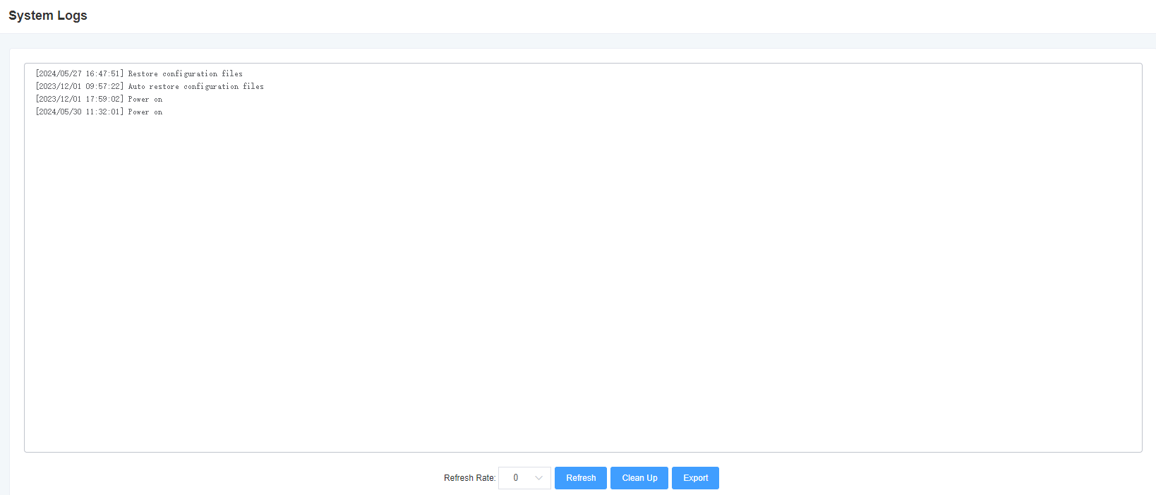
8.2 System Log
Figure 8-2-1 System Log Output
8.3 Core Service Logs
Figure 8-3-1 Core service log output
8.4 SIP Log
Figure 8-4-1 SIP log output
8.5 BIST Log
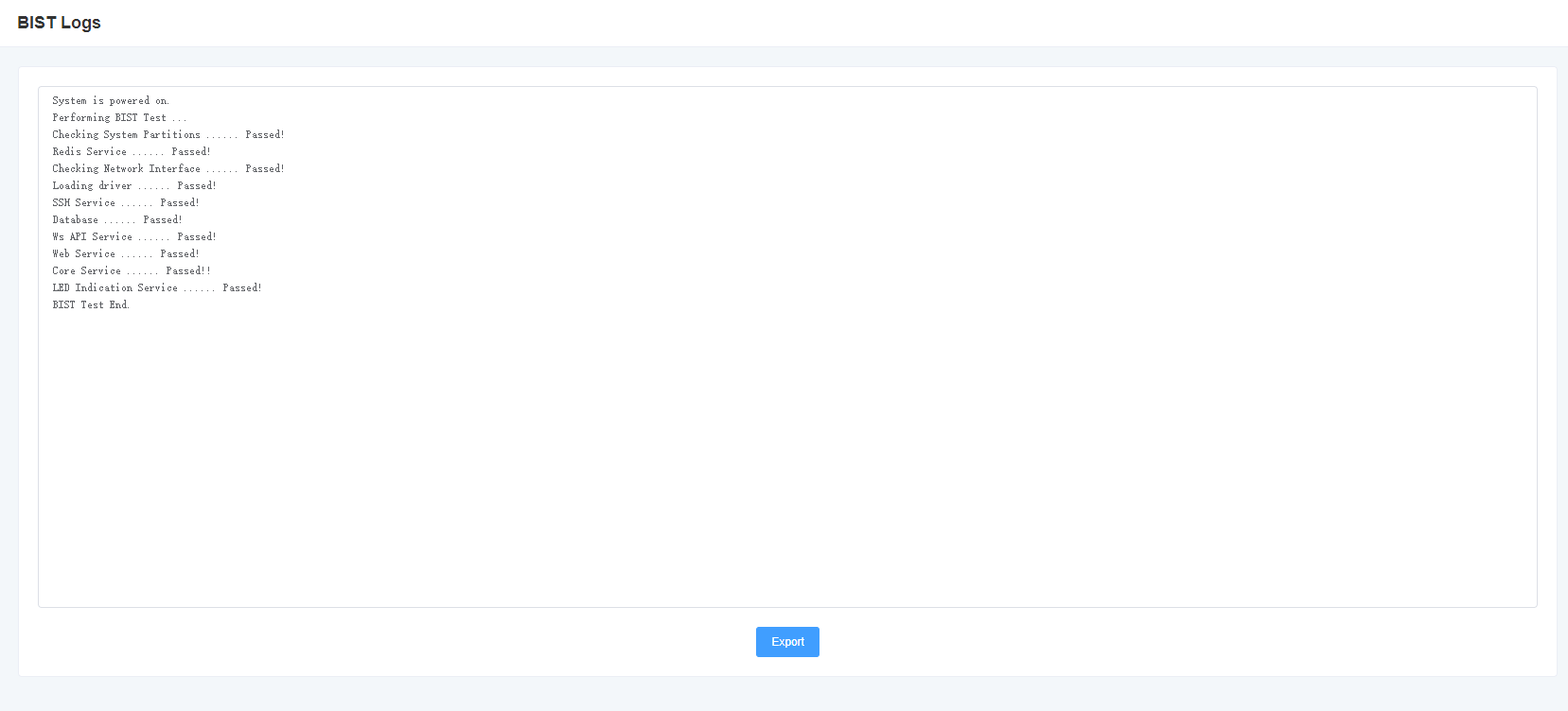
Figure 8-5-1 BIST log output
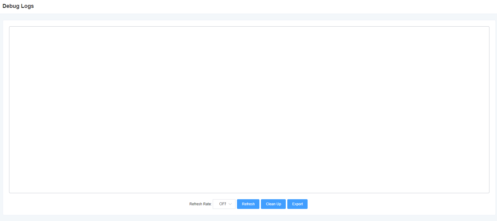
8.6 Debug Log
Figure 8-6-1 Debug Log Output
8.7 CDR
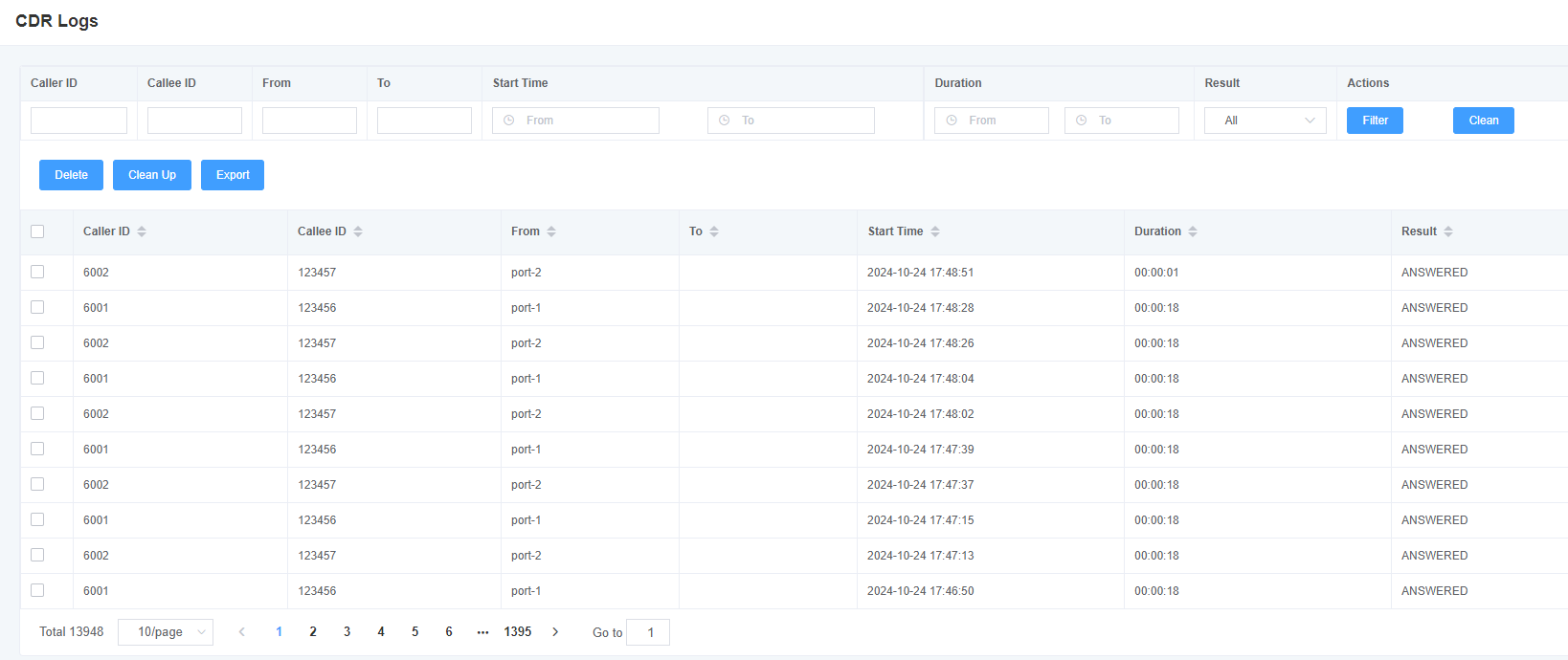
You can view the details of each call in this page. If you need to search for a specific record, you can use the filtering function. Figure 8-7-1 Call Record
