X204P/E Hardware Manual
- Chapter 1 Overview
- Chapter 2 Hardware Installation
- Chapter 3 FXS,FXO,BRI and E1
- Chapter 4 Reference Table of Contents
Security Notes
![]()
1. (a) The X204P/E is subject to specific national safety regulations during application.
2. (a) Turn off the power before installing the X204P/E.
3. To prevent damage to the board by electrostatic induction, snap the card stopper to the PC with a screw
on the PC to achieve grounding.
4. (b) Static ring is essential during installation.
5. Please follow the instruction steps.
Chapter 1 Overview
1.1 X204P/E Introduction
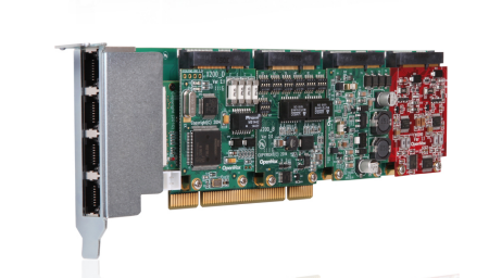
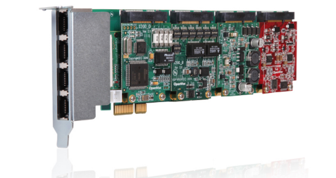
The X204 series cards are general purpose devices for connecting to the PSTN (Public Switched Telephone Network) area with the telephone network. This is achieved through analog connections to the FXO (Outside Switching Office) port, telephone handsets to the FXS (Outside Switching Station) port, digital line connections to the BRI (Basic Rate ISDN) interface, and the E1 (Basic Rate ISDN PRI) port. the X204 series cards allow Asterisk to connect to the telephone network, creating an office-type telephony environment. OpenVox’s X204 Hybrid Phone Card is a PCI2.2 compliant card that supports 3 interfaces: FXO/FXS, BRI and E1. Users can choose the number of FXO/FXS modules according to their individual needs. The BRI port can be configured as a separate TE or NT mode via a jumper. It provides 4 simultaneous voice calls over 2 ISDN BRI lines, turning legacy ISDN BRI into powerful voice through IP equipment and providing a soft migration path from ISDN technology to the new world of voice over IP. e1 supports T1, E1, and J1 environments and is available on a per card or per port basis optional, and supports industry standard telephony and data protocols, including primary rate ISDN (both North American and European) protocol families for voice, PPP, Cisco, HDLC, and Frame Relay data modes. Both line side and torso side interfaces are supported.
The X204 series cards work well on open source Asterisk® systems, allowing users to experience the full performance and versatility of Asterisk®.
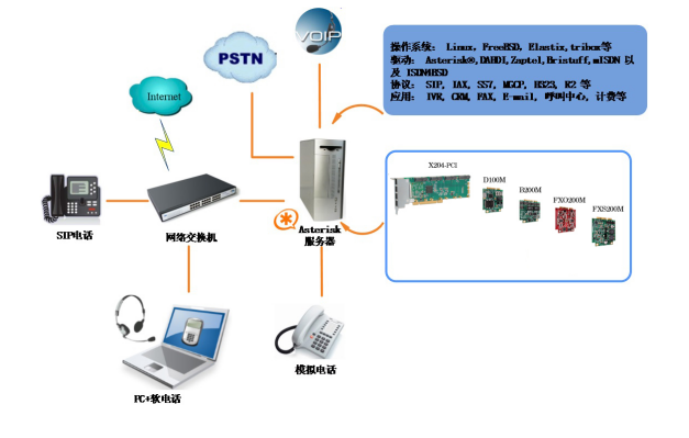
Figure 1 Topology diagram
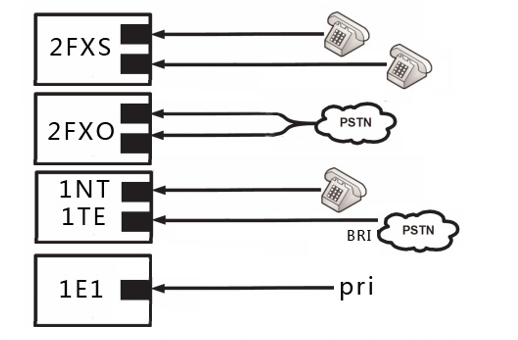
Figure 2 FXO/FXS/BRI/E1 application
Typical Applications
- Alternative Channel Bank applications
- SOHO-level communication applications
- SMB level communication applications
- Terminal connection for analog phone or PSTN line applications
- High performance ISDN BRI voice boards
- ISDN BRI private automatic switch
- ISDN BRI network routing
- ISDN BRI test equipment
- ISDN PBX trunking
- VoIP platform building
- IVR Service Application
- “Meet-Me” conference bridge
- VoIP gateway (SIP and IAX2 support)
- Legacy PBX/IVR Services
- Voice, data routers
- PRI/SS7/R2 compatible network or CPE
1.2 Key Features
BRI Features
- Supports TE/NT mode
- Single card supports up to 4 channels of concurrent calls on 2 ISDN BRI lines
- Board TE mode BRI module or PRI module can be used as a transceiver synchronization clock and does not require a clock source line to the board
T1/E1/J1 Features
- Industry’s first interrupt number adjustable digital voice card
- Adjustable interrupt frequency
- Compatible with all commercially available motherboards
- 1-port T1/E1/J1 PCI interface voice card
FXS/FXO Features
- Caller ID and call waiting
- ADSI phone
- Loop start signaling support
- Adjustable interrupt routing design
- Adjustable interrupt frequency
- Compatible with all commercially available motherboards
- Up to 2 simultaneous PSTN calls (per FXO200M module)
- PCI Express 1.0+ support
- 1 PCI bracket with 4 RJ45 connectors
- RoHS
Certification
- CE, FCC, A-Tick certification
- Issabel
Card Configuration
The X204 series cards are available in a variety of configurations, each of which can be made up of a single module or a combination of multiple modules, in any combination that suits your needs.
Chapter 2 Hardware Installation
The following items should be noted when setting up the X204 series cards.
2.1 Slot
X204 series cards are compatible with industry standard PCI and PCI-E slots. Users should first check which slots are available on the motherboard and whether they are compatible with X204 series cards. The slot schematic is shown below.
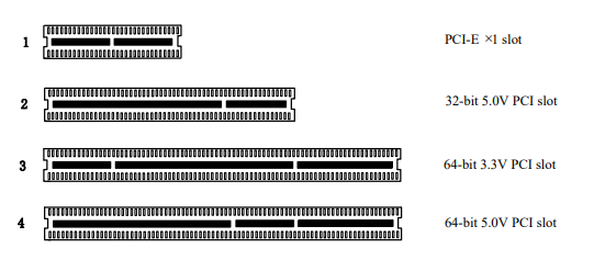
Figure 3 PCI and PCI-E slots
2.2 Hardware Installation
- (a) First familiarize yourself with the board and power down the computer.
- Install the antistatic wrist strap and then open the chassis.
- Remove the bracket placeholder and insert the card into the PCI or PCI-E slot. As shown in Figure 4 below.
- All analog phone lines are plugged into the FXO port (corresponding to the red module), and all analog phones are more required to plug the board, perforated area into the FXS port (corresponding to the green module), or provide the BRI RJ11-to-RJ45 cable (need to confirm the BRI jumper setting is correct).
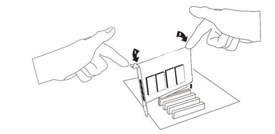
Figure 4 Plug-in card diagram
Note: The unit must be connected to a telecommunications network using a line network approved by your country, e.g. Australia is only compliant with the use of power lines AS/CAS008:2010.
Note: Only connect supervised equipment (approved for use in a specific country) to the telecommunication network voltage circuit port.
2.3 Connecting Timing Cables
The timing port allows up to three X204 Series cards to share the same synchronization (clock) source from a BRI line provider, or to provide a consistent synchronization source across multiple cards. Relative to fax mode and some voice applications prevents failures due to a clock slice on a second or third X204 Series card.
2.4 FXO/ FXS, BRI and E1 Connectivity
The FXS/FXO on the X204 series card has one RJ45 port split into two RJ11 connectors, the BRI has one RJ45 port split into two RJ45 connectors, and the E1 does not need to be connected to a breakout box.
Chapter 3: FXS, FXO, BRI and E1
The X204 series cards are available in a variety of configurations, each consisting of a combination of FXS, FXO, BRI and/or E1 modules, which can be identified by color.
- FXS-External Switching Station (green module)
- FXO-External Switching Office (red module)
- BRI-Basic Rate ISDN (green module)
- E1-Basic Rate ISDN PRI (green module)
The following is an overview of these four modules and their use on Asterisk servers.
Note: Please ask professional to install this card, users should not operate it without permission.
FXS Module
The FXS module is used by the X204 series cards to initiate and send ringing voltage to FXO devices such as analog phones. Due to the modular design, you can activate additional ports at any time with more FXS daughter cards.
FXO Modules
The FXO module consists of an X204 series card to determine the analog telephone line (PSTN). FXO module enables all calls to pass through this feature, which is supported by any standard analog telephone line. The phone receives calls forwarded to the FXO device. When it receives a voltage from the FXS device, the phone rings. Thanks to the modular design, additional ports can be activated at any time with more FXO daughter cards.
BRI module
In the BRI module you can set the port NT or TE mode, please refer to Figure 5 for information visualization.
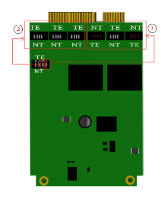
Figure 5 Jumper Settings
Channel ①/②: When the channel is dialed to TE mode, the power supply S/T interface is enabled; when the channel is dialed to NT mode, the power supply S/T interface is disabled.
E1 module
The default mode is E1 mode, if you change to T1 mode, when adding parameters, you need to load the driver.
T1 mode: modmodprobe d100m t1e1override=0
E1 mode: modprobe d100m t1e1override=1
Two configuration files need to be modified.
/etc/dahdi/system.conf
span=1,1,0,esf,b8zs
bchan=1-24
dchan=25
/etc/asterisk/dahdi-channels.conf
; Span 1: D100M1/0 “OpenVox D100M (E1|T1) Card 0/0” CCS/HDB3/CRC4 RED
group=0,11
context=from-pstn
switchtype = euroisdn
signalling = pri_cpe
channel => 1-31
context = default
group = 63
Clock source
BRI mode and E1 mode both have clock sources, there is no need to connect any clock source interface, just modify the master and slave clocks in the configuration file.
/etc/dahdi/system.conf
Example.
# Span 1: D100M1/0 “OpenVox D100M (E1|T1) Card 0/0” CCS/HDB3/CRC4 RED
span=1,1,0,ccs,hdb3,crc4 #The middle number “1” represents the master clock
# termtype: te
bchan=1-15,17-31
dchan=16
# Span 2: B200M/1 “OpenVox B200M (NT|TE) Card 1 Span 1” AMI/CCS RED
span=2,0,0,ccs,ami # The middle number “0” stands for from the clock
# termtype: te
bchan=32-33
hardhdlc=34
Chapter 4 Reference List
www.openvox.cn
www.digium.com
www.asterisk.org
www.voip-info.org
www.asteriskguru.com
Warm Tips.
Users who encounter any problems during installation and use, please find answers and leave comments on OpenVox forum or wiki.
Appendix A Hardware Specifications
– Weight, Size
Weight(g) :144g
Size(cm) :20cm*7.8cm
– Interface
RJ48 interface
PCI 3.3V or 5V PCI 2.2 or higher
PCI-E PCI-E ×1, PCI-E ×2, PCI-E ×4, PCI-E ×8 and PCI-E ×16 slots
– Environment
Temperature: 0 ~50°C (working) – 40 ~125°C (storage)
Humidity: 10 ~ 90% non-condensing
– Power Consumption
Voltage: 3.3V, 5V, 12V
Power loss: 18.25W max
-Hard and software configuration requirements
RAM 128+ MB
Linux kernel 2.4.X or 2.6.X
CPU 800+ MHz
Appendix B Pin Assignments
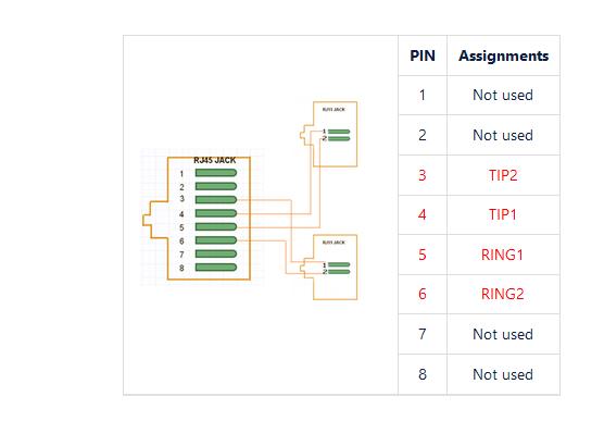
Table B-1 RJ11 Telecom Port Connector for FXO/ FXS
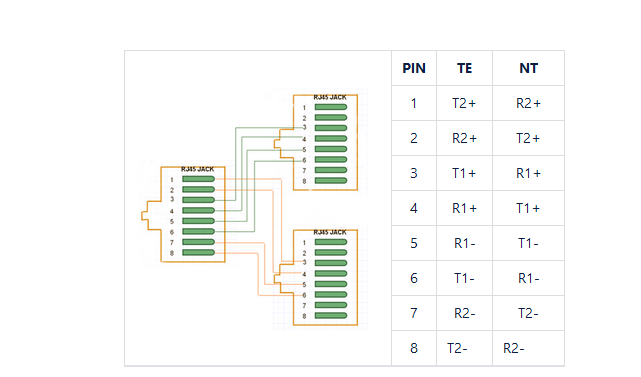
Table B-2 RJ45 ISDN BRI S/ T Port Connectors
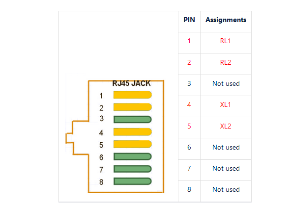
Table B-3 RJ11 Port Telecom Connectors for E1
