WTU series wireless service board consists of two models: WTU-G which supports 2G band and WTU-L which supports 3G/4G band, each module provides 4 channels of 2G/3G/4G. Each WTU series wireless service board comes with its own master control, which is an independent gateway system and can easily form a hybrid gateway with other service boards in the UCP chassis.
WTU series can bring you excellent voice services, supporting G.711U, G.711A, GSM, G.722, G.726, G.729 voice codecs, flexible SMS services and HTTP-based API interfaces. The WTU series wireless service boards are fully compatible with VoIP system platforms such as Asterisk, 3CX, FreePBX, FreeSWITCH and VOS, providing users with more diverse telecom access methods and lowering communication costs.
Product Details
OpenVox WTU Series Wireless Service Boards |
||
|---|---|---|
Product Model |
WTU-G |
WTU-L |
Module Type |
GSM |
LTE |
Number of channels |
4 |
|
Supported Bands |
GSM: 850/900/1800/1900MHz
|
WTU-L-CE China/India WTU-L-E Europe/Middle East/ WTU-L-AU Australia/ LTE FDD: B1/B3/B5/B8 Africa/Korea/Thailand New Zealand / Taiwan / Brazil LTE TDD: B38/B38/B40/B41 LTE FDD: B1/B3/B5/B7/B8/B20 LTE FDD: B1/B2/B3/B4/B5/B7/B8/B28 TD-SCDMA: B34/B39 LTE TDD: B38/B40/B41 LTE TDD: B40 CDMA: BC0 GSM: B3/B8 GSM: B2/B3/B5/B8 GSM: 900/1800MHz |
Wattage |
28W |
|
Weight (without antenna) |
164g |
|
Size (without antenna, lugs) |
124mm*185mm*21mm |
|
SIM Card |
Hot-Swap |
|
Working environment temperature |
0℃ ~ 40℃ |
|
Humidity of working environment |
10% ~ 90% |
|
Storage environment temperature |
-20℃ ~ 70℃ |
|
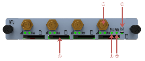
WTU Wireless Service Board

1: System status indicator led
2: Power status indicator led
3: Reset button
4: SIM card slot
5: Antenna

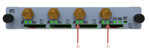
1: SIM card working status indicator led
2: SIM card signal strength indicator led
Connection to WTU Wireless Service Board
WTU series wireless service board is designed for easy configuration and installation. To connect the WTU series wireless service board, please follow these steps.
1、Make sure there is a switch board plugged into the top of the UCP chassis, and plug the Ethernet cable into the LAN port of the switch board.
2、Insert the WTU series wireless service board into the chassis slot.
3、Plug the power adapter into the chassis power port and connect it to the wall outlet to power on.
Configure WTU Wireless Service Board
The default factory IP address is: 172.16.80.X (where X indicates the slot number where the WTU service board is plugged into the chassis slot)
WTU series wireless service board can be configured via PC's web browser, please refer to the following steps.
1、Please use the correct specification AC/DC to power your UCP chassis.
2、Open the Web browser on your PC
3、Enter the IP address of WTU series wireless service board in the address bar of the browser
4、Enter the administrator password to access the Web configuration menu (by default, the administrator user name and password is admin)
Note: Please make sure your computer has an IP address in the range of 172.16.80.XXX so that you can access the Web GUI of the WTU Series Wireless Service Board.
How to determine whether the WTU wireless service board is working properly
After WTU series wireless service board is inserted into the chassis, you can judge whether it is working normally by the following ways.
1, UCP chassis power on, PWR power indicator is always on.
2、When the WTU series wireless service board system is running normally, the run status indicator SYS is in green slow flashing state (green light is on for 2s, and flashing for 0.1s).
3、Before the SIM card is inserted, the SIM card working status indicator is in the state of long off, and the SIM card signal strength indicator is in the state of red slow flashing (light 0.5s, off 0.5s).
4、After inserting the SIM card, the SIM card working status indicator and SIM card signal strength indicator are in green long light state.
5、The Web GUI of WTU wireless service board can be accessed normally by computer web browser.
Parent topic: Quick Installation Guide