Navigation: Product Description > X1911/X1960/X1981 Product Architecture >
A shelf of the X1960 provides a space for placing and connecting X1960 internal components. It also protects the components from contamination and external damage.
Appearance
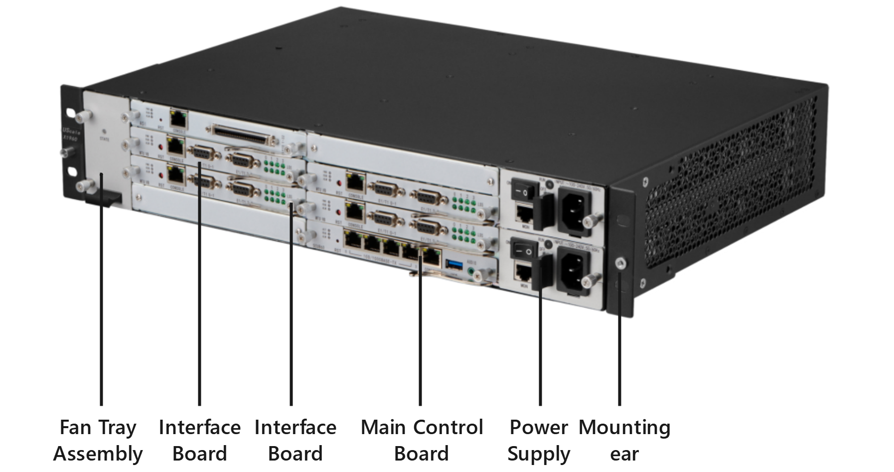
The X1960 adopts the standard 2U (88.9 mm)shelf. The dimensions (H x W x D) of the shelf are 86.1 mm x 442 mm x 310 mm. The self can be installed in a 19-inch cabinet that meets the International Electrotechnical Commission (IEC) standard. Figure 1 shows the X1960 front panel.
Figure 1 Front panel

Slots
Slots are located on the front panel of the shelf. The X1960 provides one main control board slot, seven interface board slots, two power supply sockets, and one fan tray assembly slot, as shown in Figure 2.
ϒ⁄Slots 0 to 6 are service board slots, which are used to install the MTU, ASI, and OSU boards.
ϒ⁄Slot 7 is the main control board slot, which is used to install the SCU board.
Figure 2 Slot distribution

![]()
ϒ⁄The number of X1960 interface boards is determined by the system capacity. Filler panels must be inserted into blank slots.
ϒ⁄To ensure that basic services are functioning properly, at least one SCU board must be configured for the X1960.
Parent Topic: X1911/X1960/X1981 Product Architecture