Navigation: Operation and Maintenance > Administrator Guide > Routine Maintenance >
This topic describes how to check the grounding system of the unified gateway and how to use the earth resistance tester to measure the grounding resistance. The grounding system of the unified gateway refers to the yellow and green ground cables from the grounding terminal of the shelf to the grounding system in the equipment room.
Reference Standard
ϒ⁄All contacting points are in good condition without loose connection or corrosion.
ϒ⁄Grounding resistance is less than or equal to 5 ohm.
Checking the Grounding System
ϒ⁄Procedure
1.Check whether the ground cables in the shelf are damaged, aged, eroded, or burnt by electrical arc.
2.Check whether the connecting terminals and captive screws of all ground cables in the shelf are connected firmly and are not eroded.
3.Use a multimeter to test if all parts in the shelf are well grounded.
a.Adjust the multimeter to the ohm range. Connect one probe to a fixed grounding point in the equipment room (lengthen the probe cable when necessary). Use another probe to measure the grounding points in the shelf one after the other. To ensure accuracy, the resistance measured at each grounding point should be about five ohms.
b.If the resistance measured at a grounding point is more than five ohms, check the ground cable, grounding terminal, and captive screw of this grounding point at once, and accordingly take proper measures.
4.Use the earth resistance tester to measure the grounding resistance of the grounding network in the equipment room. The grounding resistance should not be more than five ohms. See section Measuring the Grounding Resistance for details.
ϒ⁄Troubleshooting
1.If the connection line is in poor contact, correct the connection.
2.If the connection line is corroded, replace it.
3.If the grounding resistance fails to meet requirements, reconstruct the grounding environment.
Measuring the Grounding Resistance
ϒ⁄Procedure
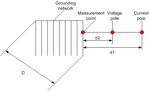
Use the earth resistance tester to measure the grounding resistance of the grounding network in the equipment room. During measurement, place the voltage pole and the current pole of the earth resistance tester as shown in Figure 1.
Figure 1 Layout of poles of the earth resistance tester

1.The distance from the current pole to the edge of the grounding network is d1. The value d1 is four to five times of the maximum diagonal length (D) of the grounding network.
2.The distance from the voltage pole to the edge of the grounding network is d2. The value d2 is 50% to 60% of the value d1.
3.When measuring the resistance, move the voltage pole three times along the line between the current pole and the grounding network. The distance moved each time is 5% of d1. If the resistance values measured for three times are almost equal, take the average value of these three values as the grounding resistance of the grounding network.
4.If d1 cannot be four to five times of D, set d1 to two times of D and d2 to D in the areas with relatively even earth resistance rate. Set d1 to three times of D and d2 to 1.7 times of D in the areas with uneven earth resistance rate.
![]()
5.Place the current pole and the voltage pole vertical to the line or the underground metal pipe.
6.Do not measure the grounding resistance immediately after raining.
ϒ⁄Troubleshooting
If the grounding resistance fails to meet requirements, reconstruct the grounding environment.
Parent Topic: Routine Maintenance