Navigation: Installation >
In order to ensure stable operation of the devices, ensure that the device is properly grounded and adopt a proper cabling method.
Grounding Methods
Table 1 describes the grounding methods.
![]()
The cross-sectional area of a PGND cable is no less than 4 mm2. A PGND cable shall be as short as possible during construction, and coiling is forbidden.
Table 1 Device grounding methods
Equipment Room Condition |
Grounding Method |
A ground bar is available. |
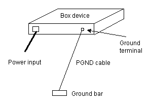
Method 1: Use a PGND cable to connect the ground hole of the device directly to the ground bar, as shown in the following figure.
|
Method 2: Use a PGND cable to connect the ground hole of the device to the ground terminal of the cabinet so that the ground hole of the device is connected to the ground bar through the cabinet. When using this method, ensure that the ground terminal and ground bar are reliably connected. |
|
No ground bar is available. |
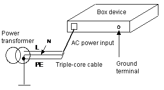
Method 1: If the device uses a 220 V AC power supply, use the PE cable of the AC power supply to ground the device. When using this method, ensure that that the PE cable is properly grounded in the power distribution room or on the AC power transformer, and that all cables used between the ground segment and device are triple-core cables.
|
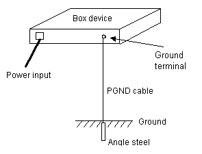
Method 2: Bury a ground electrode, and use a PGND cable to directly ground the device. When using this method, ensure that mud ground exists near the device and that the ground electrode can be buried.
The ground electrode can be angle steel or a steel pipe (made of zinc-coated steel) with a length no less than 0.5 m. The dimensions of the angle steel must be at least 50 mm x 50 mm x 5 mm (L x W x H). The inner wall thickness of the steel pipe must be at least 3.5 mm. The PGND cable shall be welded to the ground electrode, and the surface of the welding point must be coated with antirust paint. NOTE: You are advised to spray some salt water on the soil near the ground electrode to reduce the resistivity of the soil and improve the grounding effect of the ground electrode. |
Verifying Grounding
Method: Measure the ground voltage and resistance.
Item |
Measurement Method and Description |
Ground voltage |
When the device is powered on, use a multimeter to measure the voltage between the device shell and ground (which can be the ground bar or PE cable of the AC power supply). If the voltage is greater than 10 V, the grounding effect is not good. Locate the cause and improve the grounding effect. |
Ground resistance. |
When the device is powered off, use a multimeter to measure the voltage between the device shell and ground (which can be the ground bar or PE cable of the AC power supply). If the resistance is greater than 10 ohms, the grounding effect is not good. Locate the cause and improve the grounding effect. |
Cabling Specifications
To prevent call quality from being affected by interference among cables, comply with the following cabling rules:
ϒ⁄The PGND cable is grounded based on the nearby principle, and is properly connected to the ground bar.
ϒ⁄The length of the PGND cable does not exceed 45 cm. The PGND cable shall be as short as possible, and coiling is forbidden. If the length of the PGND cable exceeds 45 cm, relocate the ground bar.
ϒ⁄The PGND cable shall not be in parallel or twisted with signal cables.
ϒ⁄Signal and power cables are separated, and analog and digital signal cables are separated.
Parent Topic: Installation


