RIU Wireless Trunking Gateway Module User Manual
Profile version: R1.1.0
Product Version:R1.1.0
Declaration:
This manual is intended only as an operating guide for users.
No unit or individual may reproduce or excerpt part or all of the contents of this manual without the written permission of the Company, and may not distribute it in any form.
This book agreement
1. Command line formatting conventions
| Format | Meaning |
| / | Command line multi-level paths separated by “/” |
| [ ] | Indicates that the part enclosed by “[ ]” is optional in the command configuration. |
| // | A line starting with “//” is a comment line. |
| # | “#” is the linux system command input identifier, “#” followed by the user input linux operation command, all linux command input is completed, you need to press [Enter] enter key to execute the command;
In Linux scripts, # is followed by a comment. |
| mysql> | indicates the database operation, and “>” is followed by the database operation command that requires user input. |
2. GUI formatting conventions
| Format | Meaning |
| < > | The “< >” brackets indicate the name of the button, e.g. “Click the <OK> button” |
| [ ] | The square brackets “[ ]” indicate the window name, menu name, data table and data type field, e.g. “Pop up [New User] window” |
| / | Multi-level menus and multiple field descriptions of the same type are separated by a “/”. For example, [File/New/Folder] multi-level menu means [Folder] menu item under [New] submenu of [File] menu. |
1 Device Panel Introduction
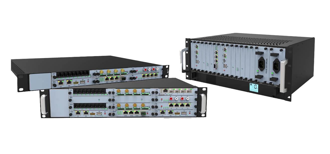
1.1 Schematic diagram of the chassis
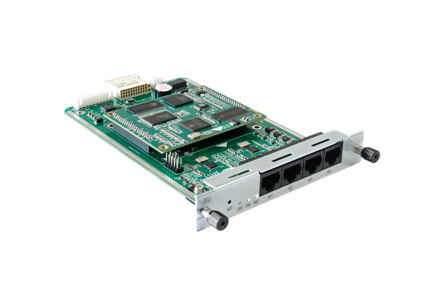
Module for chassis UCP1600/2120/4131 series
Figure 1-1-1 Frontal diagram
1.2 Module schematic
Figure 1-2-1 Schematic diagram of RIU module
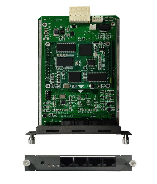
As shown in Figure 1-1-1, the meaning of each logo is as follows
- Indicator lights: There are three indicators from left to right: fault light E power light P, run light R; the power light is always green after normal operation of the equipment, the run light is green flashing, the fault light does not light.
- reset key: short press to reset, long press for more than 5 seconds to close the watchdog, E light on. Long press for more than 10 seconds to restore the temporary IP address 10.20.30.1, restore the original IP after power failure and reboot.
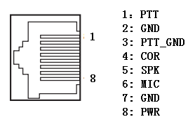
- The W interface is defined as follows
2 Login
Login to the wireless cluster gateway module web page: Open IE and input http://IP, (IP is the wireless gateway device address, the default IP is 10.20.40.40), enter the login screen as shown in Figure 1-1-1 below.
Initial user name: admin, password: 1
Figure 2-1-1 Wireless Trunking Gateway Module Login Interface

3 Network information configuration
3.1 Modify static IP
The static network address of the Wireless Trunk Gateway can be modified in [Basic/Network Configuration], as shown in Figure 3-1-1.
Figure 3-1-1

Note: At present, the wireless cluster gateway IP acquisition method only supports static, after modifying the network address information, you need to reboot the device to take effect.
3.2 Registration server configuration
In [Basic/Sip Server Settings], you can set the IP addresses of the primary and backup servers for the registration service, and the primary and backup registration methods, as shown in Figure 3-2-1:
Figure 3-2-1

The primary and backup registration methods are divided into: no primary and backup switching, registration priority to the primary softswitch, and registration priority to the current softswitch.
The order of registration: primary softswitch, standby 1 softswitch, standby 2 softswitch, and standby 3 softswitch.
* Explanation: No primary and backup switching: Only to the primary softswitch. Registration to the primary softswitch takes precedence: the primary softswitch registration fails to register to the backup softswitch. When the primary softswitch is restored, the next registration cycle registers with the primary softswitch. Registration priority to the current softswitch: registration failure to the primary softswitch registers to the backup softswitch. When the primary softswitch is restored, it always registers with the current softswitch and does not register with the primary softswitch.
3.3 Communication port configuration
In [Advanced /SIP settings], you can set the communication port and RTP port range, as shown in Figure 3-3-1:
Figure 3-3-1

Softswitch Communication Port: The port for SIP communication between Wireless Trunking Gateway and IPPBX. RTP port minimum: the lower limit of the range of the port that sends and receives RTP packets. RTP port maximum: the upper limit of the range of the port for sending and receiving RTP packets.
Note: This configuration is not recommended to be modified randomly.
4 User Configuration
4.1 Adding user numbers
The user number of the wireless trunk gateway can be added in [Basic/Channel settings], as shown in Figure 4-1-1:
Figure 4-1-1

Click “Add” to bring up the dialog box for entering user number information, as shown in Figure 4-1-2:
Figure 4-1-2

Channel number: for 0, 1, 2, 3 User number: the phone number corresponding to the line
Registration user name, registration password, registration period: the account number, password and interval time of each registration used when registering to the platform.
Hotline number: the called phone number corresponding to the hotline function key
*Description:
- Time to initiate registration = Registration period * 0.85
- The wireless gateway uses only four channels and can only add four users
When adding numbers, you can configure function keys, media, gain, chase call, PSTN, RET, while adding numbers supports batch adding and deleting.
4.2 Media Configuration
After adding the wireless trunking gateway user, you can modify the user’s voice encoding method, DTMF type, RTP transmission interval, DTMF load under [Advanced/Media Configuration], and click ” in the corresponding user operation column.
![]()
“Modify icon, pop up as shown in Figure 4-2-1:
Figure 4-2-1

- Speech encoding format: including G711a, G711u
- DTMF type: including RFC2833, SIPINFO, INBAND (in-band)
- RTP send interval: the time interval for voice packets to be sent, default 20ms (not recommended to modify)
- DTMF load: payload, default use 101
4.3 PSTN_COR Configuration
In [Advanced/PSTN_COR], you can configure user PSTN_COR information, as shown in Figure 4-3-1:
Figure 4-3-1

- COR polarity: Vitex vertex2100/vertex2200,high level active
Moto GM3688, active low
- COR detection suppression time: the interval between two COR snatches (used to open COR snatches)
- Voice COR priority: four lines and IP phones speak at the same time, open to ensure that the four-line users are the main
4.4 NET_COR Configuration
In [Advanced/NET_COR], you can configure user NET_COR information, as shown in Figure 4-4-1:
Figure 4-4-1

- COR type: select voice detection (VOX), voice dual pass, talk to IP phones
Select Off for half-duplex calls with POC users
- Voice Detection Threshold: Detects voice packets on the Network side and can be configured with a detection threshold. The higher the threshold value, the louder the voice requirement to activate the COR signal, and vice versa.
4.5 Gain configuration
In [Advanced/Gain Configuration], you can configure the gain type of the user, as shown in Figure 4-5-1:
Figure 4-5-1

- A->D gain: the gain from the analog side to the digital side.
- D->A gain: the gain from the digital side to the analog side.
4.6 Callback configuration
In [Advanced/Chase Call Configuration], you can configure the user’s chase call type, interval time, and how to handle new calls when chasing, as shown in Figure 4-6-1:
Figure 4-6-1

- 4XX chase call: When the wireless gateway user initiates a call, the chase call function is triggered when the softswitch replies with a “4XX” message indicating that the call has failed.
- When BYE chase call: the wireless gateway user initiates a call, and when the softswitch replies with a “BYE” message to indicate the end of the call, the chase call function is triggered.
- New call in chase: The wireless gateway user is triggered to chase the call function, and the processing mode is configured when there is a new call incoming at this time.
- Calling interval: The time interval for initiating a call to the user.
5 Advanced Configuration
5.1 System Configuration
In [system configuration], the features of echo cancellation, silent compression, time synchronization, long time no voice packet processing, and prompted voice are generally used. <span style=”color: #ff0000″><strong>Note: System compatibility mode uses 4w mode</strong></span>
5.1.1 Echo cancellation
In [Advanced/Call settings], you can turn on and off the echo cancellation function, as shown in Figure 5-1-1:
Figure 5-1-1

When this feature is turned off, calls with wireless trunking gateway users may generate echo, which affects the call quality and is turned off by default.
5.1.3 Time synchronization
In [Advanced /System Configuration], you can select the time synchronization method, as shown in Figure 5-1-3:
Figure 5-1-3

5.1.3.1 SIP200OK synchronization
When “SIP200OK Synchronization” is selected in [Advanced Configuration/System Configuration], the time of the 200OK message received from the softswitch after the user initiates registration is synchronized with the server during the registration period.
5.1.3.2 NTP server synchronization
In [Advanced /System settings], when you select “NTP Server Synchronization”, a field for entering an NTP server will appear at the bottom, as shown in Figure 5-1-4:
Figure 5-1-4

After entering the NTP server IP address, the wireless cluster gateway synchronizes with this NTP server once during the cycle.
5.1.4 Long time no voice packet processing
In [Advanced /System Configuration], you can select the way to handle long periods of no voice packets, as shown in Figure 5-1-5:
Figure 5-1-5

- Way one: no processing; after a long time detecting no voice timeout, no processing is done and the call is still maintained.
- Way 2: Release the call; after a long time of not detecting voice timeout, the call is released and the call ends.
- Mode 3: Rebuild the call Failure to release; after a long time detecting no voice timeout, initiate a re-invite to continue the call
5.1.5 Reminder voice function
In [Device/prompt], you can turn on and off the Remind Voice function, as shown in Figure 5-1-6:
Figure 5-1-6
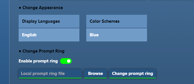
Function description: After the switch is turned on, the wireless gateway users to establish a call to put a sound to establish a call, users can upload their favorite voice file, the file supports au format, the uploaded voice file name must be ring.au voice file only one, will repeat the replacement
5.3 Dialing Rules
The dialing rules can be set in [Advanced Configuration/Dialing Rules], and the dialing rules are in number map mode. Equivalent to the ‘#’ key
The number map rules are as follows:
- Dialing rules support the use of numbers, “x”, “[]”.
“x” stands for any digit; “[]” stands for the range of digit values.
For example, if you enter the dialing rule “1[3,4][2,3-7]xx”, it means that the first digit is 1, the second digit is 3 or 4, and the third digit is 2 or a number between 3 and 7 with 5 or more digits.
- Longest match: When multiple dialups all match exactly, the longer rule is chosen to execute.
For example, if you configure the dialing rules for “7X” and “75X”, enter the number 75, it will match the dialing rules for 75X.
* Note: Dialing numbers that end with “#” will not be matched with dialing rules.
5.4 Channel switching
In [Advanced /Channel Switching], the channel of channel 0 can be selected, as shown in Figure 5-4-1, where
Figure 5-4-1

Note: _ At present, channel switching is only for 0 channels, when using the channel selection need to select the supported channels
5.5 Time Setting
In [Advanced /Time settings], you can configure various time-class parameters of the wireless trunking gateway system, as shown in Figure 5-5-1, where:
Figure 5-5-1

- Receive User Number Duration: The duration of DTMF reception when the handset is off-hook and the intercom key is allowed. Default:12S
- Key interval: the maximum time interval between two adjacent key presses. Default 3S
- No Voice Packet Max Length: The maximum time that a call lasts without voice. Default: 300S
- Long call duration: the timeout duration of not calling. Default: 120S
- Dial tone length: the length of time to play dial tone to the intercom when the handset is off-hook. Default:3S
- Ringing duration: the duration of ringing when the handset listens to the ringback tone, when ringing, no DTMF is received from the intercom. default: 1S
- Stop ringing duration: when listening to the ringback tone, the duration of stop ringing, when not ringing, can receive DTMF from the intercom. default: 6S
- Intercom listen busy tone length: the length of the intercom listen busy tone when the handset hangs up, or the opposite end hangs up. Default:3S
6 Status queries
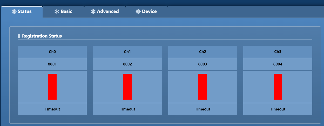
6.1 Registration Status
In [Status /Registration Status], you can view the user registration status information, as shown in Figure 6-1-1:
Figure 6-1-1
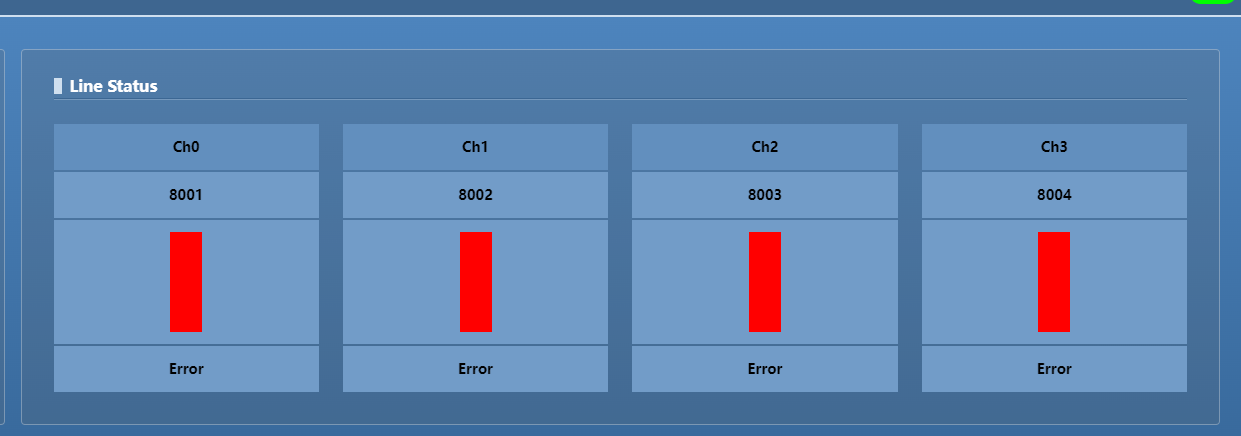
6.2 Line Status
In [Status /Line Status], you can view line status information, as shown in Figure 6-2-1:
Figure 6-2-1
7 Function key usage instructions
In [Advanced/Code settings], you can set the function keys when adding wireless gateway users, as shown in Figure 7-1-1:
Figure 7-1-1

7.1 Dialing function codes
The default dialing code is “*9#“, when you make a dialing call by handheld, you can directly input “*9#+phone number (e.g. *9#8888)” and then press “OK” key and then press PTT to make the call.
7.2 Picker Function Code
The default function code of the picker is “*7#“, when you make a dialing call by hand, you can first enter “*7#” and press PTT, clear the “*7#” function code after listening to the dialing tone, enter the phone number, press “OK”, and then press PTT to make a call.
7.3 Hang-up function code
Hang-up function code default is “*0#“, handheld and phone in the call, handheld input “*0#” and press “OK”, then press PTT, handheld listen to busy tone, the call is over.
7.4 Hot Line Function Code
- When the function key is opened: the default hotline function code is “*8#“, the wireless trunk gateway user configured hotline number, handheld input “*8#” and press “OK” and then press PTT, the hotline number corresponds to the phone ringing.
- When opening the PPT hotline: press PTT directly and the hotline number rings directly
7.5 Turning off the chase function code
The default code to turn off the chase function is “*1#”. If the wireless trunk gateway user turns on the chase function and triggers the chase function after the call fails, within the time interval of initiating the next chase, the handheld enters “*1#” and presses “OK” and then presses PTT to stop initiating the chase.
8 System administration
8.1 Log Management
Log servers, log levels, etc. can be set in [Device/Log Management], as shown in Figure 8-1-1, where:
Figure 8-1-1

Log level: including “error”, “alarm”, “simple”, “process”, “debug”, “detailed”, corresponding to the log lv.0 to lv.6. The higher the level, the more detailed the log.
Log server address: IP of the log server.
Log server receive port: the port of the log server to receive logs.
Send log port: The port of the wireless gateway to send logs.
490 chip debug port: port for debugging 490.
8.2 Software Upgrade
The wireless trunking gateway system can be upgraded in [Device/Software Upgrade], as shown in Figure 8-2-1:
Figure 8-2-1

Click <Browse>, select the eagos upgrade program in the pop-up window, select it and click <Open>, then finally click the <Upgrade> button on the web page. The system will automatically load the upgrade package, and will reboot automatically after the upgrade is completed.
8.3 Equipment Operation
In [Device/Device Operation], you can perform: recovery, reboot, system backup rollback, data import and export operations on the wireless trunk gateway system, as shown in Figure 8-3-1, where:
Figure 8-3-1

Restore factory settings: Clicking the <Restore> button will restore the Wireless Trunked Gateway configuration to factory settings, but will not affect the system IP address related information.
Reboot the device: Clicking the <Reboot> button will reboot the device for the Wireless Trunked Gateway operation.
System Backup: Clicking the <Backup> button will backup DriverTest, Driver_Load, KeepWatchDog, VGW.ko, VoiceGw, VoiceGw.db to the directory in /var/cgi_bakup/backup.
System Rollback: Click <Rollback> button, it will use the files after system backup and overwrite the current files. It will restart automatically after the rollback.
Data Export: Click the <Export> button to automatically package VoiceGw.db. After that, a pop-up window will appear to select the download storage location and download it to the local PC via webpage.
Data import: Click <Browse>, and select the zip file downloaded to the local PC after data export in the pop-up window, and click Open. Click the Import button on the web page again, and it will restart automatically after successful import.
Note: The wireless gateway system backup will only keep one backup. That is, only the last backup system program and data can be saved for rollback.
8.4 Version information
The version numbers of programs and library files related to the wireless cluster gateway can be viewed in [Status/Version Information], as shown in Figure 8-4-1:
Figure 8-4-1

8.5 Account Management
The password for web login can be changed in [Device/Login Operations], as shown in Figure 8-5-1:
Figure 8-5-1

Change password: Fill in the current password in the old password, fill in the new password and confirm the new password with the same modified password, and click the <Modify Password> button to complete the password change.
Default Password: Click <Default Password? button to automatically restore the login password of the web page as the default.
The default login name is: “admin”; the password is “1”.
9 Appendix I: Function key usage instructions
9.1 Continuous Dialing Function Code
The default dialing code is “*9#“, when you make a dialing call by handheld, you can directly input “*9#+phone number (e.g. *9#8888)” and then press “OK” key and then press PTT to make the call.
9.2 Picker Function Code
The default function code of the picker is “*7#“, when you make a dialing call by hand, you can first enter “*7#” and press PTT, clear the “*7#” function code after listening to the dialing tone, enter the phone number, press “OK”, and then press PTT to make a call.
9.3 Hang-up function code
Hang-up function code default is “*0#“, handheld and phone in the call, handheld input “*0#” and press “OK”, then press PTT, handheld listen to busy tone, the call is over.
9.4 Hot Line Function Code
- When the function key is opened: the default hotline function code is “*8#“, the wireless trunk gateway user configured hotline number, handheld input “*8#” and press “OK” and then press PTT, the hotline number corresponds to the phone ringing.
- When opening the PPT hotline: press PTT directly and the hotline number rings directly
9.5 Turning off the chase function code
The default code for closing the chase function is “*1#“, the user of wireless trunk gateway turns on the chase function and triggers the chase function after the call fails, within the time interval of initiating the next chase, the handheld enters “*1#” and presses “OK” and then presses PTT, no more chase calls will be initiated.
