AIU-8 Analog Interface Unit User Manual

OpenVox Communication Co Ltd
AIU-8 Analog Interface Unit User Manual
Version 1.0
Address: Room 624, 6/F, Tsinghua Information Port, Book Building, Qingxiang Road, Longhua Street, Longhua District, Shenzhen, Guangdong, China 518109
Tel: +86-755-66630978, 82535461, 82535362
Business Contact: [email protected]
Technical Support: [email protected]
Business Hours: 09:00-18:00(GMT+8) from Monday to Friday
URL: www.openvox.cn
Thank You for Choosing OpenVox Products!
Confidentiality
Information contained herein is of a highly sensitive nature and is confidential and proprietary to OpenVox Inc. No part may be distributed, reproduced or disclosed orally or in written form to any party other than the direct recipients without the express written consent of OpenVox Inc.
Disclaimer
OpenVox Inc. reserves the right to modify the design, characteristics, and products at any time without notification or obligation and shall not be held liable for any error or damage of any kind resulting from the use of this document.
OpenVox has made every effort to ensure that the information contained in this document is accurate and complete; however, the contents of this document are subject to revision without notice. Please contact OpenVox to ensure you have the latest version of this document.
Trademarks
All other trademarks mentioned in this document are the property of their respective owners.
Revise History
| Version | Release Date | Description |
| 1.0 | 25/06/2023 | First Version |
1. Overview
1.1 What is AIU-8 Analog Interface Unit?
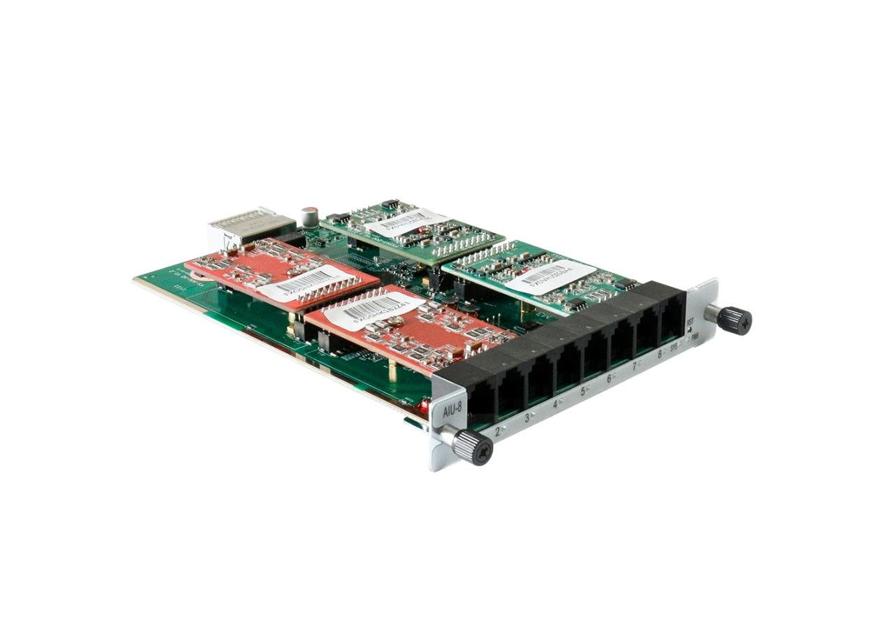
The AIU-8 module is a FXO/FXS analog interface boards for UCP1600/2120/4131 series chassis; The AIU-8 module provides 4 FXO and 4 FXS ports, 8 FXO ports and 8 FXS ports.
The AIU-8 is developed for interconnecting a wide selection of codecs including G.711A, G.711U, G.722, G.726, G.729A, iLBC. AIU-8 use standard SIP protocol and compatible with leading VoIP platform, IPPBX and SIP servers, such as Asterisk, Issabel, 3CX, FreeSWITCH, BroadSoft and VOS VoIP operating platform.
1.2 Product Appearance
The picture below are the interfaces and indicator light description of AIU-8 analog gateway module.
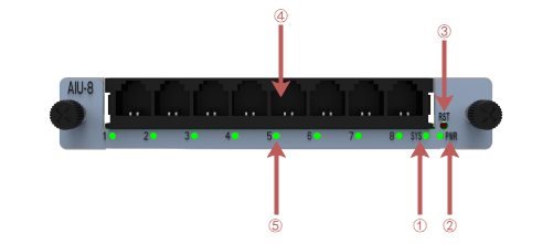
Figure 1-2-1 AIU-8 Front Panel
1: System Status Indicator
2: Power Status Indicator
3: Reset button
4: Channel Interface
5: Channel Status Indicator
1.3 Main Features
System Features
- NTP time synchronization and client time synchronization
- Support modify username and password for web login
- Update firmware online, backup/restore configuration file
- Abundant Log Info, Automatically Reboot, Call status display
- Language selection (Chinese/English)
- Open API interface (AMI), support for custom scripts, dialplans
- Support SSH remote operation and restore the factory settings
Telephony Features
- Support volume adjustment, gain adjustment, call transfer, call hold, call waiting, call forward, Caller ID display
- Three way calling, call transfer, dial-up matching table
- Support T.38 fax relay and T.30 fax transparent, FSK and DTMF signaling
- Support ring cadence and frequency setting, WMI (Message Waiting Indicator)
- Support echo cancellation, jitter buffer
- Support customizable DISA and other applications
SIP Features
- Support add, modify & delete SIP accounts, batch add, modify & delete SIP accounts
- Support multiple SIP registrations: Anonymous, Endpoint registers with this gateway, This gateway registers with the endpoint
- SIP accounts can be registered to multiple servers
Network
- Network type: Static IP, Dynamic
- Support DDNS, DNS, DHCP, DTMF relay, NAT
- Telnet, HTTP, HTTPS, SSH
- VPN client
- Network Toolbox
1.4 Physical Information
Table 1-4-1 Description of Physical Information
| Interface | 4FXS4FXO/8FXS/8FXO |
| Weight | 160g |
| Dimension | 130*21*200mm |
| Temperature | -20~70°C (Storage) |
| 0~50°C (Operation) | |
| Operation humidity | 10%~90% non-condensing |
| Max power | 12W |
1.5 Software
Default IP: 172.16.80.X(X is the slot number of the chassis; If it is slot 3 of UCP1600, the IP address is 172.16.80.3.)
Username: admin
Password: admin
Please enter the default IP in your browser to scan and configure the module you want.
Figure 1-5-1 Login Interface

2. System
2.1 Status
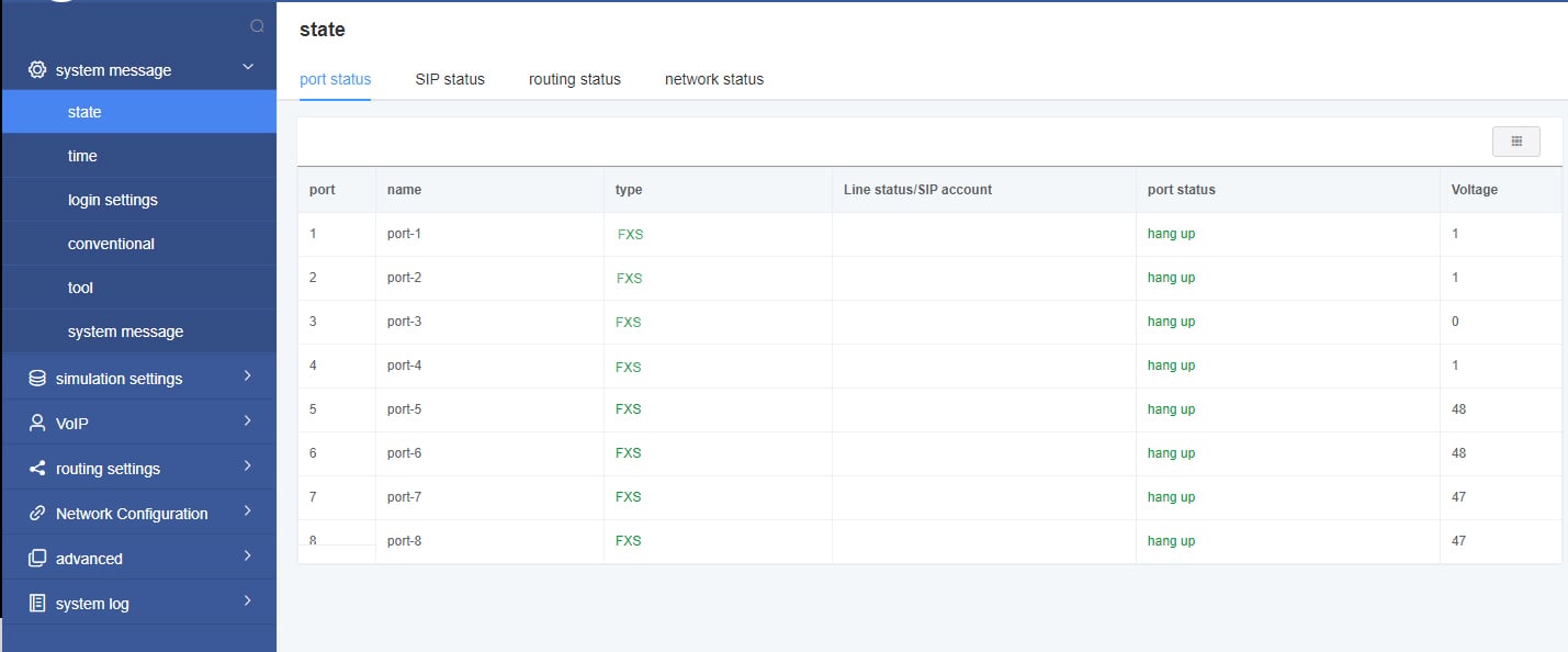
On the “Status” page, you will see Port/SIP/Routing/Network information on display.
Figure 2-1-1 System Status
2.2 Time
Table 2-2-1 Description of Time Settings
| Options | Definition |
| System Time | Your gateway system time. |
| Time Zone | The world time zone. Please select the one which is the same or the closest as your city. |
| POSIX TZ String | Posix time zone strings. |
| NTP Server 1 | Time server domain or hostname. For example, [time.asia.apple.com]. |
| NTP Server 2 | The first reserved NTP server. For example, [time.windows.com]. |
| NTP Server 3 | The second reserved NTP server. For example, [time.nist.gov]. |
| Auto-Sync from NTP | Whether enable automatically synchronize from NTP server or not. ON is enable, OFF is disable this function. |
| Sync NTP | Sync time from NTP server. |
| Sync Client | Sync time from local machine. |
For example, you can configure like this:
Figure 2-2-1 Time Settings
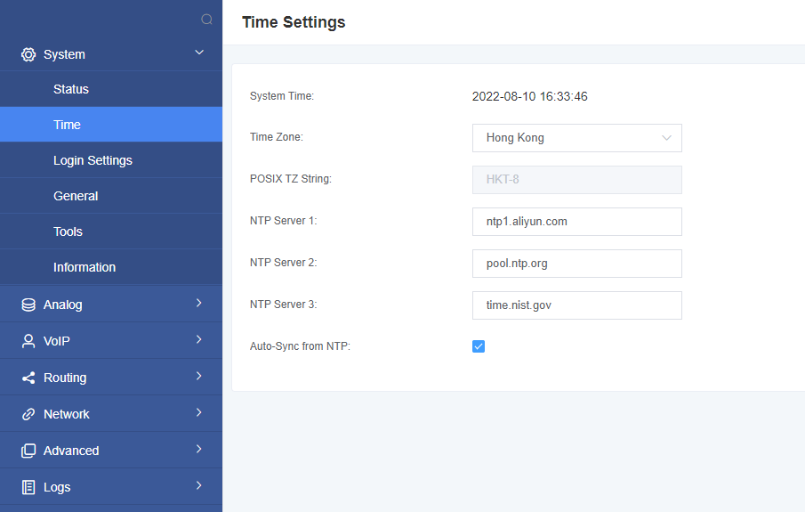
You can set your gateway time Sync from NTP or Sync from Client by pressing different buttons.
2.3 Login Settings
Your gateway doesn’t have administration role. All you can do here is to reset what new username and password to manage your gateway. And it has all privileges to operate your gateway. You can modify both your “Web Login Settings” and “SSH Login Settings”. If you have changed these settings, you don’t need to log out, just rewriting your new user name and password will be OK.
Table 2-3-1 Description of Login Settings
| Options | Definition |
| User Name | Define your username and password to manage your gateway, without space here. Allowed characters “-_+. < >&0-9a-zA-Z”.
Length: 1-32 characters. |
| Password | Allowed characters “-_+. < >&0-9a-zA-Z”. Length: 4-32 characters. |
| Confirm Password | Please input the same password as ‘Password’ above. |
| Login Mode | Select the mode of login. |
| HTTP Port | Specify the web server port number. |
| HTTPS Port | Specify the web server port number. |
| Port | SSH login port number. |
Figure 2-3-1 Login Settings
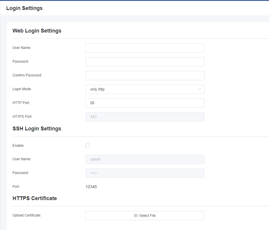
Notice: Whenever you do some changes, do not forget to save your configuration.
2.4 General
2.4.1 Language Settings
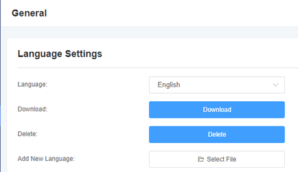
On our gateway products, you can set different languages according to your needs.
First, you need to turn on the “Advanced” mode.
And then “Download” the current language pack of the system.
Then click the “Browse” option.
After importing the language pack you need, click the “Add” button.
And it will take effect without restarting the gateway.
Figure 2-4-1 Language Settings
2.4.2 Scheduled Reboot
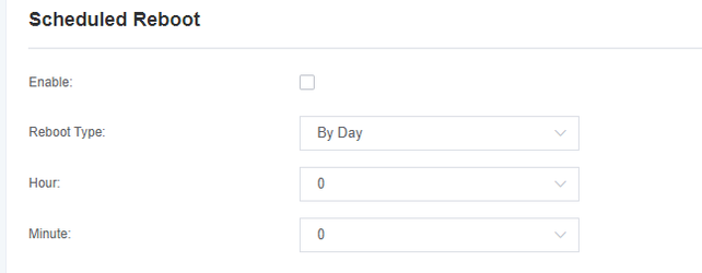
You can enable the automatic restart function to make your gateway restart after working for a certain period of time to achieve higher work efficiency.
Figure 2-4-2 Scheduled Reboot
2.5 Tools
In the tool page, users can restart the gateway, upgrade firmware, upload and backup configuration files, and restore factory settings.
The analog gateway supports individual system restart or Asterisk restart.
Figure 2-5-1 Reboot Tools
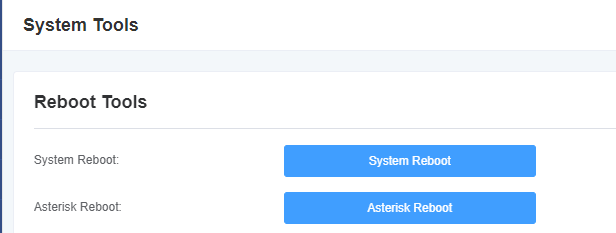
Notice: When you confirm the restart, the system will automatically end all current calls.
Table 2-5-1 Description of Reboots
| Options | Definition |
| System Reboot | This option will restart your gateway and cut off all current sessions. |
| Asterisk Reboot | This option will restart Asterisk and cut off all current sessions. |
The analog gateway provides two firmware upgrade methods, you can choose system upgrade or system online upgrade. To select the system upgrade, you need to download the relevant firmware from the OpenVox website first. The system online upgrade is an easier way with one-click upgrade.
Figure 2-5-2 Update Firmware

After configuring your gateway, you can download the current configuration file. When you need to configure other gateways of the same model or restore the gateway to factory settings, you can choose to upload this backup configuration file without the need to reconfigure the gateway .
Notice: It will take effect only if the version of the configuration file and the current firmware version are the same.
Figure 2-5-3 Upload and Backup Configuration Files

Figure 2-5-4 Voice Record

Figure 2-5-5 Restore Configuration File

Figure 2-5-6 Restore System

Notice: You can restore the gateway to factory settings by dialing. Connect the phone to the FXS port of the gateway and dial “*1*2*3*4” , then it will restore the gateway to factory settings.
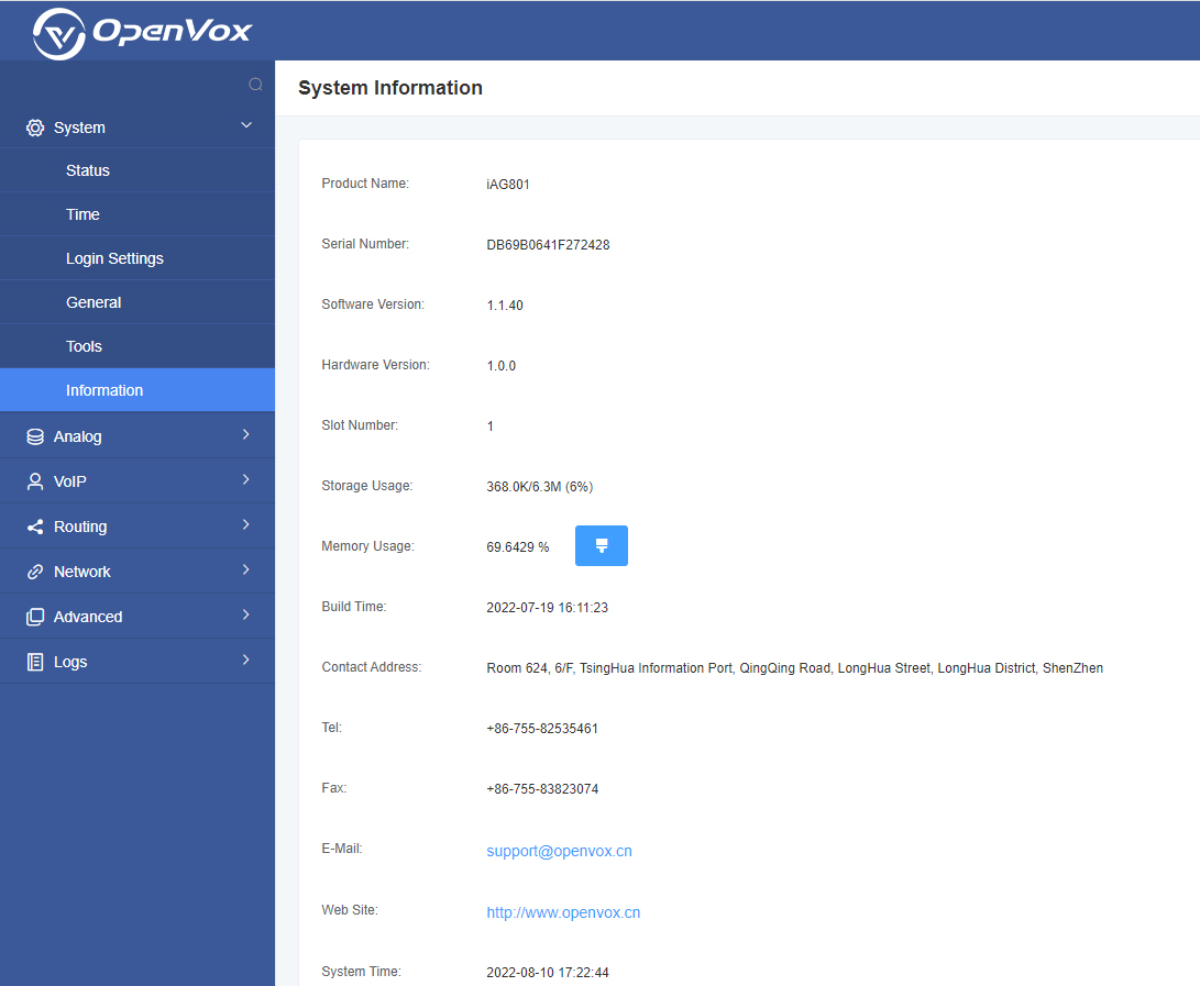
2.6 Information
On the “Information” page, there shows some basic information about the analog gateway. You can see software and hardware version, storage usage, memory usage and some help information.
Figure 2-6-1 System Information
3. Analog
You can see much information about your ports on this page.
3.1 Channel Settings
Figure 3-1-1 Channel System
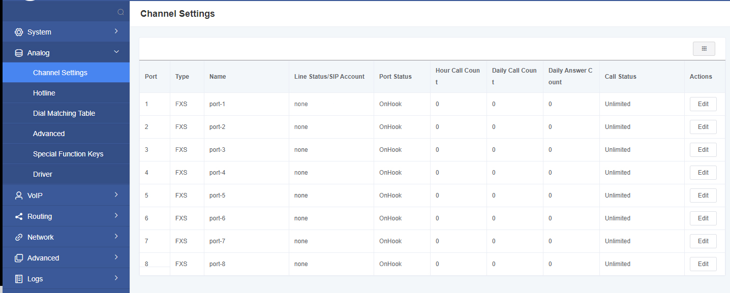
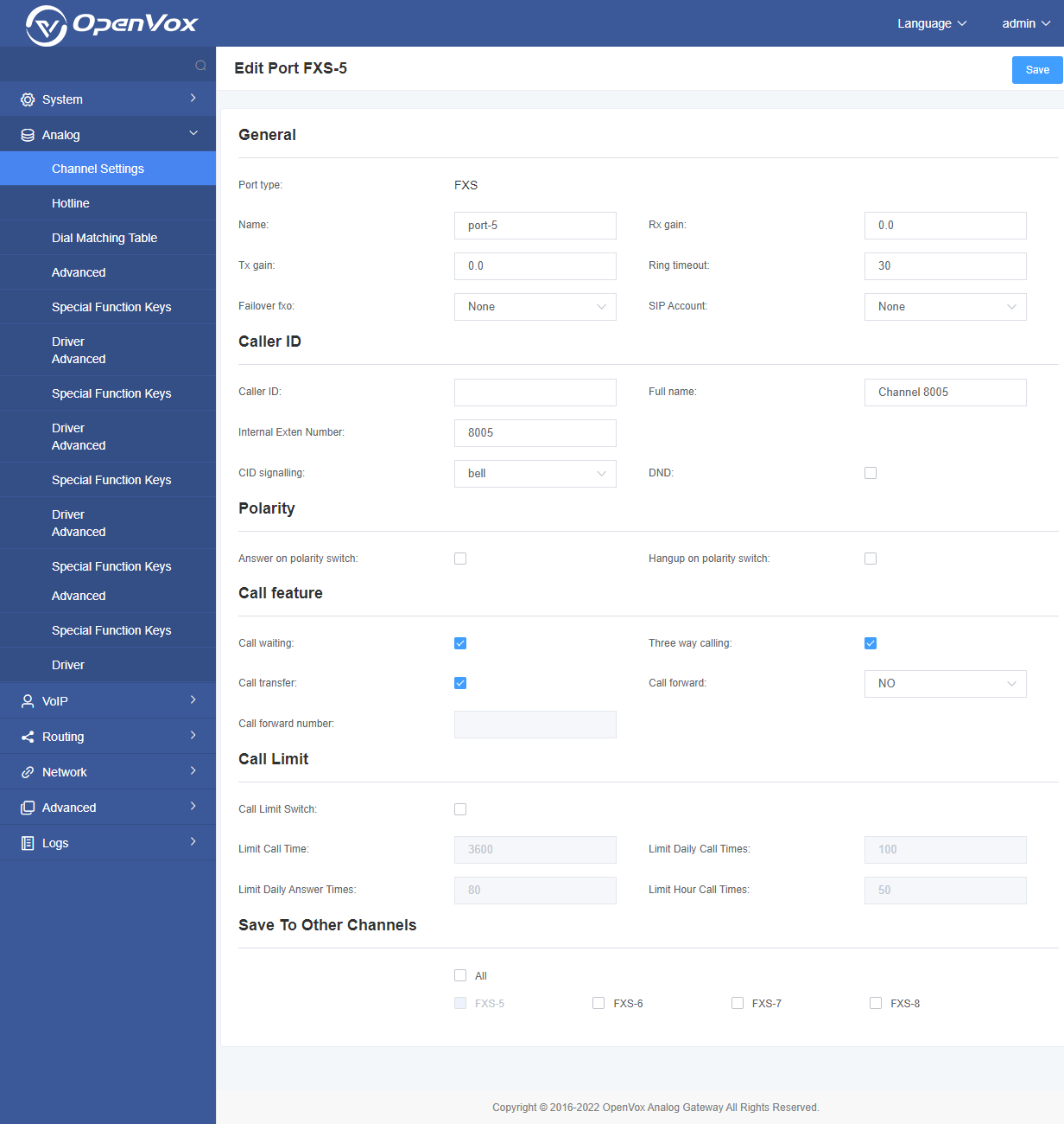
Click the button to automatically modify the corresponding port information.
Figure 3-1-2 FXS Port Configure
3.2 Hotline Settings
Call pick-up is a feature used in a telephone system, which allows one phone to answer a call on the another phone. You can set the “Time Out” and “Number” parameters individually or globally for each port. This function is realized by dialing a series of specific numbers, provided that you enable this function and set the “number” parameter correctly.
Figure 3-2-1 Pickup Settings
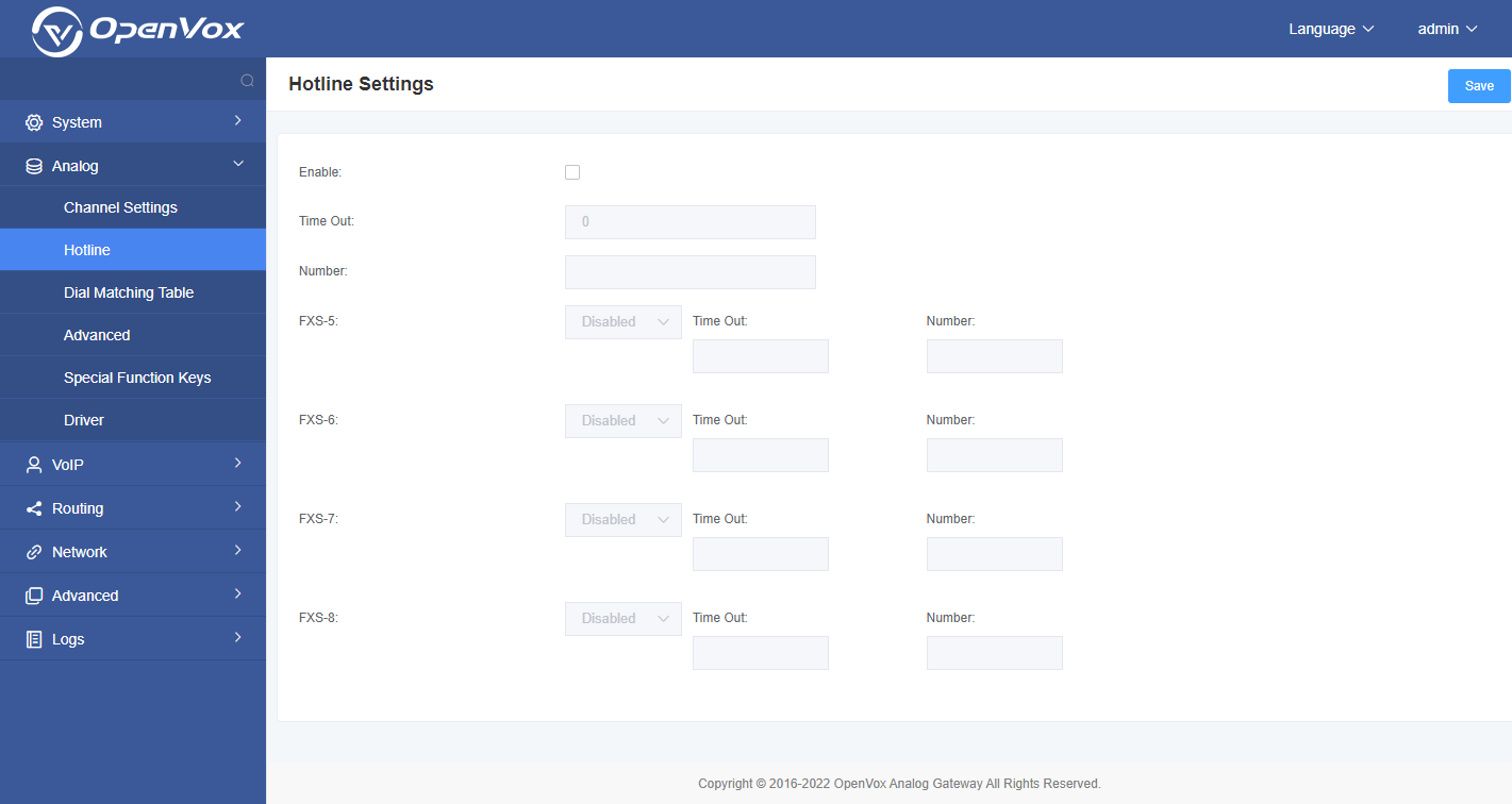
Table 3-2-1 Definition of Pickup
| Options | Definition |
| Enable | ON(enabled), OFF(disabled) |
| Time Out | Set the timeout, in milliseconds (ms).
Notice: You can only enter numbers. |
| Number | Pickup number |
3.3 Dial Matching Table
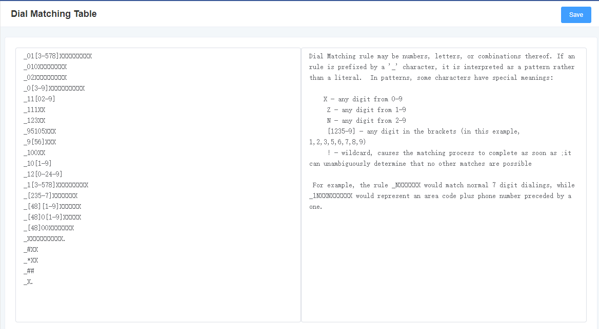
The dial matching table is to effectively judge whether the received number is complete so that it can be sent in time.
The correct use of the dial matching table can help shorten the call establishment time.
Figure 3-3-1 Dial Matching Table
3.4 Global Settings
Figure 3-4-1 General Configuration
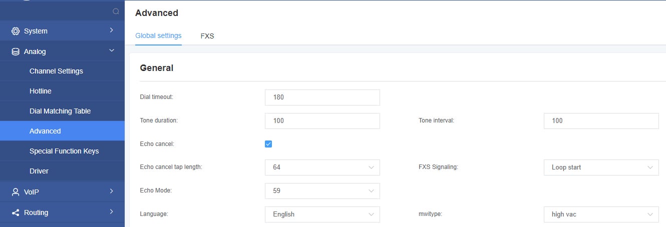
Table 3-4-1 Instruction of General
| Options | Definition |
| Dial timeout | Specifies the number of seconds we attempt to dial the specified devices. |
| Tone duration | How long generated tones (DTMF and MF) will be played on the channel. (in milliseconds). |
| Tone interval | How long between tone and tone will be played on the channel. (in milliseconds). |
| Echo cancel | Echo cancel |
| Echo cancel tap length | Hardware echo canceler tap length. |
| FXS Signaling | Default Loop start, busy tone is generated, Kewlstart, power is off, no busy tone is generated |
Figure 3-4-2 Fax Configuration

Table 3-4-2 Definition of Fax Option
| Options | Definition |
| mode | Set the transmission mode. |
| Rate | Set the rate of sending and receiving. |
| Ecm | Enable/disable T.30 ECM (error correction mode) by default. |
Figure 3-4-3 Country Configuration
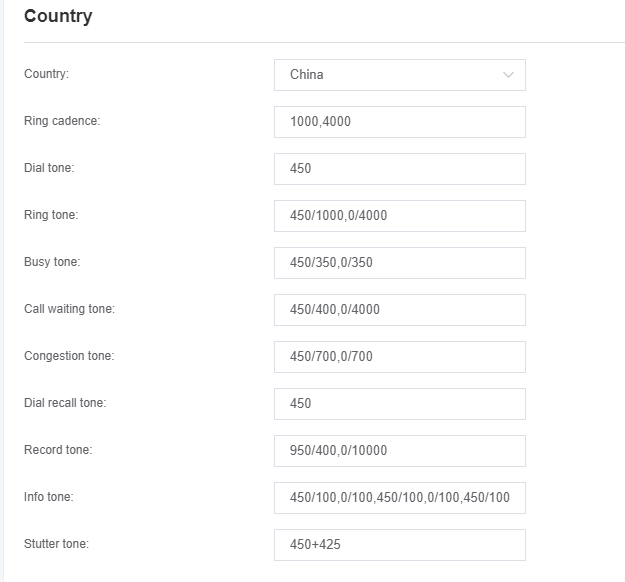
Table 3-4-3 Definition of Country Settings
| Options | Definition |
| Country | Set the signal tone standard of the country where the gateway is located. |
| Ring cadence | List of duration the physical bell rings. |
| Dial tone | Set the off-hook dial tone. |
| Ring tone | Set the prompt tone to the caller when ringing. |
| Busy tone | Set the prompt tone when busy. |
| Call waiting tone | Set the background prompt tone to play when entering the call waiting. |
| Congestion tone | Set the prompt tone to be played when congested. |
| Dial recall tone: | Set the prompt tone for the second dialing after pressing the flash key. |
| Record tone | Set the prompt tone for the recording process. |
| Special message tone | Set the prompt tone for playing special information.
(for example: the dialed number is not in the service area) |
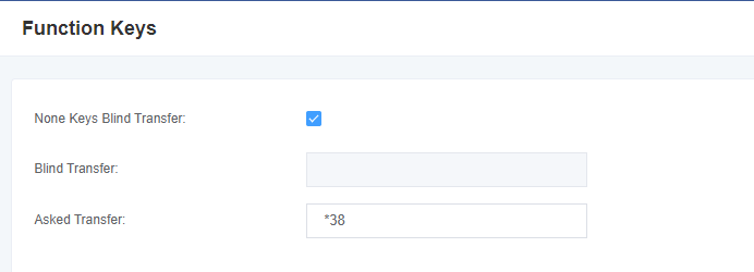
3.5 Special Function Keys
Figure 3-5-1 Function keys
3.6 Driver
Figure 3-6-1 General
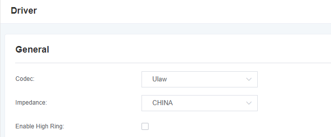
Table 3-6-1 Definition of General
| Options | Definition |
| Codec | Set the global encoding: mulaw, alaw |
| Impedance | Configuration for impedance. |
| Enable High Ring | High ring enable help. |
Figure 3-6-2 CallerID Detect
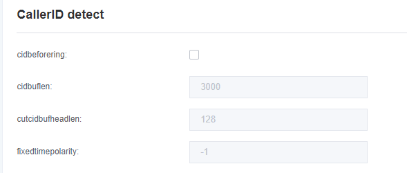
Table 3-6-2 Definition of CallerID Detect
| Options | Definition |
| cidbeforering | Switch to handle irregular CID function. |
| cidbuflen | CID media stream length byte size. |
| cutcidbufheadlen | CID media stream header length byte size. |
| fixedtimepolarity | Transmit polarity line reversal signal delay time. |
Figure 3-6-3 Hardware Gain
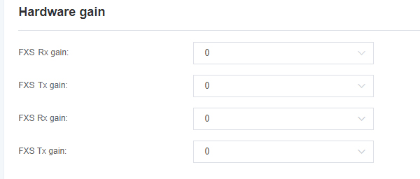
Table 3-6-3 Definition of Hardware Gain
| Options | Definition |
| FXS Rx gain | Set FXS to IP gain. Range: -35, 0 or 35. the default is 0. |
| FXS Tx gain | Set FXS to terminal gain. Range: -35, 0 or 35. the default is 0. |
4. VoIP
4.1 SIP Endpoint
On this page, the status information about the SIP account is displayed.
Figure 4-1-1 SIP Endpoints

Click the edit button to modify the corresponding SIP information.
4.1.1 Main Endpoint Settings
There are 3 kinds of registration types for choose on the VoxStack series analog gateways. You can choose “Anonymous, Endpoint registers with this gateway or This gateway registers with the endpoint”.
You can configure as follows:
If you set up a SIP endpoint by registration “None” to a server, then you can’t register other SIP endpoints to this server. (If you add other SIP endpoints, this will cause Out-band Routes and Trunks confused.)
Figure 4-1-2 Main Endpoint Settings
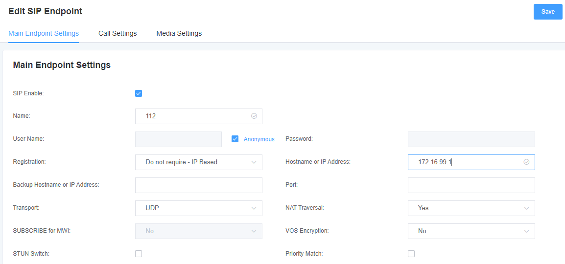
For convenience, we have designed a method that you can register your SIP endpoint to your gateway, thus your gateway just work as a server.
Figure 4-1-3 Main Endpoint Settings
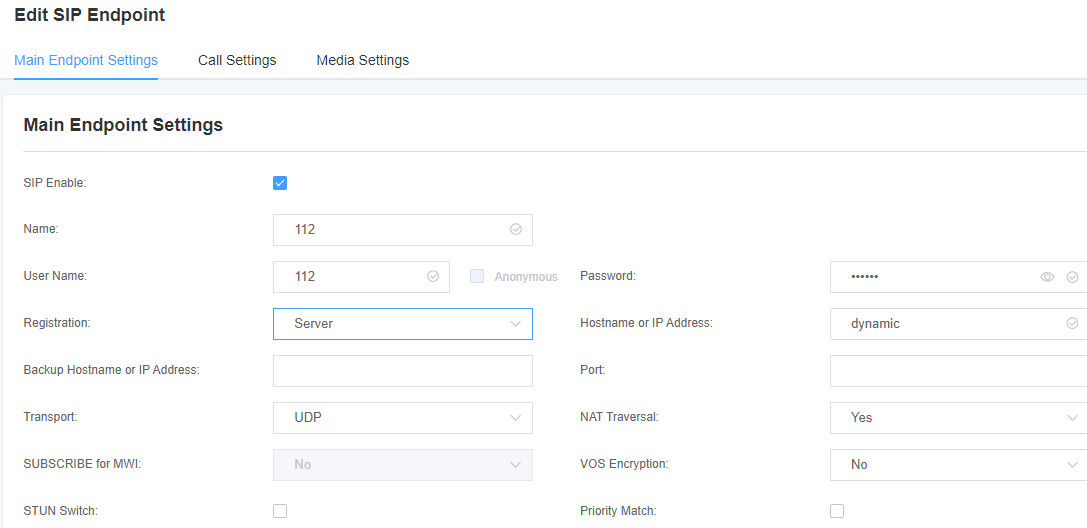
When “Gateway is registered to the endpoint”, you need to fill in the username and password, and you can register multiple SIP endpoints to the server. Due to the difference in usernames and passwords, there will be no confusion between routing and Trunks.
Figure 4-1-4 Register to Server
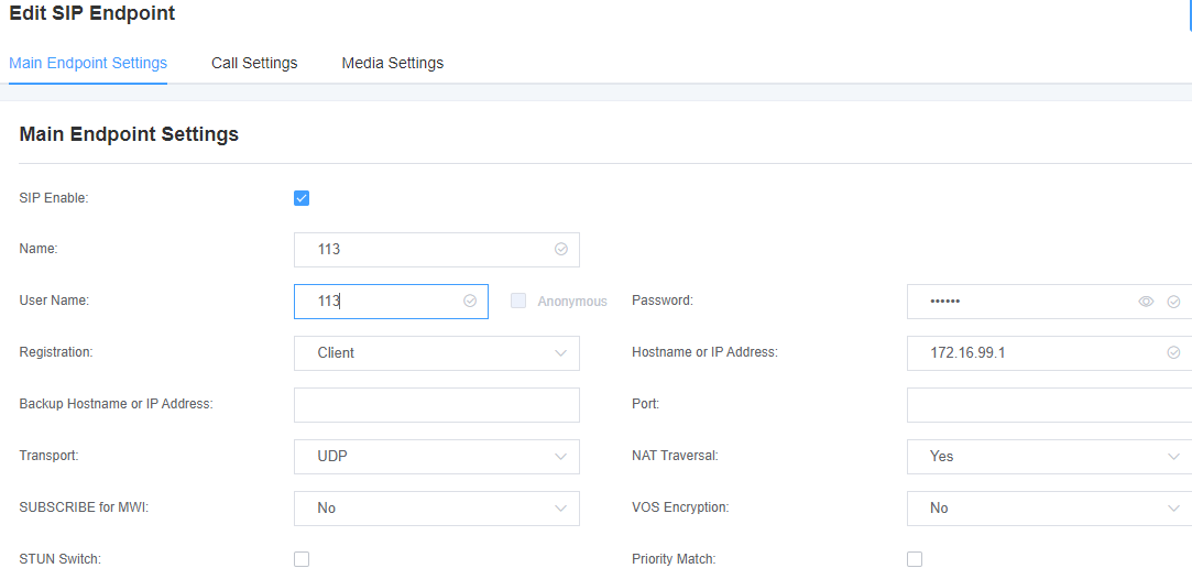
Table 4-1-1 Definition of Endpoint Settings Options
| Options | Definition |
| Name | A name which is able to read. And it’s only used for user’s reference. |
| Username | Username for authentication between the endpoint and the gateway. |
| Password | The password for authentication between the endpoint and the gateway, allowing letters. |
| Registration | None—Anonymous registration;
Endpoint registers with this gateway—The gateway is used as a server, and the SIP endpoint is registered to the gateway; This gateway registers with the endpoint—The gateway is used as a client, and the SIP terminal needs to be registered on the server. |
| Domain name or IP address | IP address or domain name of the endpoint or ‘dynamic’ .(if the endpoint has a dynamic IP address.)This needs to register. |
| Alternate domain name or IP address | Same as above.
After filling this, it is equivalent to that this account initiates registration to two domain names or IP addresses at the same time. When the account of the primary domain name or IP address expires, it will switch to the account of the alternate domain name or IP address |
| Transmission method | Set possible transmission types and order of use for outgoing transmissions.
When you use various transport protocols: UDP, TCP, TLS, the transmission type enabled for the first time is only used for outgoing messages until registration occurs. If the endpoint requires another transmission type during the registration process, the first transmission type may be changed to another transmission type. |
| NAT Traversal | Issues related to NAT addresses when incoming SIP or media sessions. |
| VOS encryption | When the endpoint is a VOS server, the encryption item needs to be used, and the parameters need to be turned on at this time |
4.1.2 Advanced: Registration Options
Figure 4-1-5 Registration Options

Table 4-1-2 Definition of Registration Options
| Options | Definition |
| Authentication User | A username to use only for registration. |
| Register Extension | When Gateway registers as a SIP user agent to a SIP proxy (provider), calls from this provider connect to this local extension. |
| Registered user name | The registered username, is the user in “register => user[:secret[:authuser]]@host[:port][/extension]” |
| User source | A username to identify the gateway to this endpoint. |
| From Domain | A domain to identify the gateway to this endpoint. |
| Port | The port number the gateway will connect to at this endpoint. |
| Quality | To check the endpoint’s connection status whether or not. |
| Qualify Frequency | How often, in seconds, to check the endpoint’s connection status. |
| Outbound Proxy | A proxy to which the gateway will send all outbound signaling instead of sending signaling directly to endpoints. |
| Customized registration switch | After opening, customers can customize the registration form by themselves. |
| Enable Outboundproxy to Host |
4.1.3 Call Settings
Table 4-1-3 Definition of Call Options
| Options | Definition |
| DTMF Mode | Set default DTMF Mode for sending DTMF. Default: rfc2833. Other options: ‘info’, SIP INFO message (application/dtmf-relay); ‘Inband’, Inband audio (require 64kbit codec -alaw, ulaw). |
| Call Limit | Set a call limit, the maximum number of calls that can be allowed at the same time. |
| Trust Remote-Party-ID | Whether or not the Remote-Party-ID header should be trusted. |
| Send Remote-Party-ID | Whether or not to send the Remote-Party-ID header. |
| Endpoint Party ID Format | How to set the Remote-Party-ID header: from Remote-Party-ID or from P-Asserted-Identity. |
| Caller ID Presentation | Whether or not to display Caller ID. |
4.1.4 Advanced: Signaling Settings
Table 4-1-4 Definition of Signaling Options
| Options | Definition |
| Inbound In-band Signaling | Whether to generate an incoming ring tone.
Never: indicates that the incoming signal is never applicable; Optional values: yes, no, never; Default value: never; |
| Allow Overlap Dialing | Allow Overlap Dialing: Whether or not to allow overlap dialing. Disabled by default. |
| Append User=Phone to URI | Whether or not to add ‘; user=phone’ to URIs that contain a valid phone number. |
| Add Q.850 Reason Headers | Whether or not to add reasonable header and to use it if it is available. |
| SDP Version Header | By default, the gateway will add a session version number to the SDP packet and if the SDP version number is modified, it will only modify the SDP session.
Turning off this option will force the gateway to ignore this SDP version number and treat all SDP data as new data. This is necessary for a device that sends non-standard SDP packets. It is turned on by default. |
| Allow Transfers | Whether or not to globally enable transfers. Choosing ‘no’ will disable all transfers (unless enabled in endpoints or users). Default is enabled. |
| Allow Promiscuous Redirection | Whether or not to allow 302 or REDIR to non-local SIP address.
Notice: Redirecting to the local system will cause a loop call, which Asterisk does not support. |
| Maximum Forward | Setting for the SIP Max-Forwards header (loop prevention). |
| Send TRYING on REGISTER | Send a 100 Trying when the endpoint registers. |
4.1.5 Advanced: Timer Settings
Table 4-1-5 Definition of Timer Options
| Options | Definition |
| Default T1 Timer | This timer is used primarily in INVITE transactions. The default for Timer.
The default T1 clock is 500 milliseconds or if you have qualify=yes it will measure the round-trip time between the running gateway and the device. |
| Call Setup Timer | If no provisional response is received within this period of time, the call will be automatically blocked. The default value is 64*T1. |
| Session Timers | There are three modes to choose from: Proactively initiate, request and run the session timer;
Only accept or run the session timer when requested by other user agents; Refuse, do not run session timers in any case. |
| Minimum Session Refresh Interval | The minimum session refresh interval (in seconds). The default is 90secs. |
| Maximum Session Refresh Interval | The maximum session refresh interval ( in seconds). The default is 1800secs. |
| Session Refresher | Session refresher, user agent client or user agent server. The default is the user agent server. |
4.1.6 Media Settings
Table 4-1-6 Definition of Media Settings
| Options | Definition |
| Media Settings | Select codec from the drop down list. Different encoding priorities choose different encoding methods. |
4.2 FXS Batch Binding SIP Accounts
If you want to bind SIP accounts in batches on the FXS port, you can configure this page.
Notice: It is only available in the “This gateway registers with the endpoint” working mode.
Figure 4-2-1 FXS Batch Binding SIP

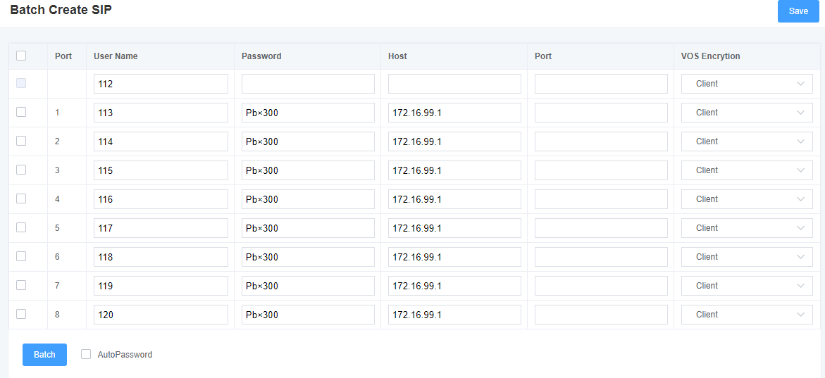
4.3 Batch Create SIP
On this interface, users can create multiple SIP accounts at one time. You can choose any registration mode.
Figure 4-3-1 Batch Create SIP
4.4 Advanced SIP Settings
4.4.1 Networking
Table 4-4-1 Regular Choice
| Options | Definition |
| UDP Bind Port | Choose a port on which to listen for UDP traffic. |
| Enable TCP | Enable request server for incoming TCP link (default is no). |
| TCP Bind Port | Choose a port on which to listen for TCP traffic. |
| TCP Authentication Timeout | The maximum number of seconds for client link verification. If the client is not authenticated before the time expires, the client will be disconnected. (Default value: 30 seconds) |
| TCP Authentication Limit | The maximum number of simultaneous links allowed in a given time. (Default value: 50 seconds) |
| Enable Hostname Lookup | Open the DNS SRV lookup for outbound calls.
Notice: The gateway is only the first host in the SRV record. This function can be used in dial-up activation to dial SIP calls on the Internet through the domain name. |
4.4.2 NAT Settings
Table 4-4-2 Definition of NAT Settings
| Options | Definition |
| Local Network | Format:192.168.0.0/255.255.0.0 or 172.16.0.0./12.
A list of IP address or IP ranges which are located inside a NAT network. This gateway will replace the internal IP address in SIP and SDP messages with the external IP address when a NAT exists between the gateway and other endpoints. |
| Local Network List | Local IP address list that you added. |
| Subscribe Network Change Event | Through the use of the “test_stun_monitor” module, the gateway has the ability to detect when the perceived external network address has changed. When the “stun_monitor” is installed and configured, “chan_sip” will renew all outbound registrations when the monitor detects any sort of network change has occurred. By default this option is enabled, but only takes effect once “res_stun_monitor” is configured. If “res_stun_monitor” is enabled and you wish to not generate all outbound registrations on a network change, use the option below to disable this feature. |
| Match External Address Locally | Only substitute the external address or domain name if it matches. |
| Dynamic and Static Selection | Dynamic hosts are not allowed to register with the IP address of static hosts. This will avoid registration errors with the same IP. |
| External TCP Port Mapping | When the gateway is behind a static NAT or PAT, the TCP port is externally mapped. |
| External IP Address | The external address of the NAT (and optional TCP port).
External IP Address = hostname[:port] specifies a static address[:port] to be used in SIP and SDP messages. Examples: External IP Address = 12.34.56.78 External IP Address = 12.34.56.78:9900 |
| External IP Hostname | The external hostname (and optional TCP port) of the NAT. |
| Hostname Refresh Interval | It will show how often to perform the hostname lookup. You can also configure a domain name. The gateway will perform a DNS query (This method is not recommended). Try to use IP and configure “externip”. |
4.4.3 STUN Settings
Table 4-4-3 Definition of STUN Settings Options
| Options | Definition |
| Start | Turn on function |
| Server Port | Default port 3478 |
| Refresh Request Interval | Time interval in seconds, default 30 seconds |
| Server IP Address/Domain Name | Server address or domain name |
4.4.4 RTP Settings
Table 4-4-4 Definition of RTP Settings Options
| Options | Definition |
| Start of RTP Port | Start range of port numbers to be used for RTP. |
| End of RTP port | End range of port numbers to be used for RTP. |
| RTP Timeout | RTP Timeout |
4.4.5 Parsing and Compatibility
Table 4-4-5 Instruction of Parsing and Compatibility
| Options | Definition |
| Strict RFC Interpretation | Check header tags, character conversion in URIs, and multiline headers for strict SIP compatibility (default is yes). |
| Send Compact Headers | Send compact SIP headers |
| SDP Owner | Allows you to change the domain of the SDP username. £¨o=£© This filed MUST NOT contain spaces. |
| Disallowed SIP Methods | When speaking back to other SIP peers, the other peers should include an “Allow” header to tell us the implementation of the SIP method. However, some peers do not include “Allow” headers or forge the methods they implement. In this case, the gateway will assume that the peer supports all known SIP methods. If you know that your SIP peer does not provide support for a specific method, then you may need to provide a list of methods that the peer does not implement in “disallowed methods”.
Notice: If your peer is real, then there is no need to set this option |
| Shrink Caller ID | The function can removes ‘(‘, ‘ ‘, ‘)’, non-trailing ‘.’, and ‘-‘ not in square brackets.
For example, the caller id value 555.5555 becomes 5555555 when this option is enabled. Disabling this option results in no modification of the caller id value, which is necessary when the caller id represents something that must be preserved. By default this option is on. |
| Maximum Registration Expiry | Maximum allowable time for incoming registration and subscription (seconds). |
| Minimum Registration Expiry | The minimum length of registration and subscription (default 60). |
| Default Registration Expiry | Default length of incoming/outgoing registration. |
| Registration Timeout | How long will it take to re-register the extension (Default 20 seconds). |
| Number of Registration Attempts | Number of registration attempts before giving up. |
4.4.6 Security and Media
Table 4-4-5 Instruction of Security and Media
| Options | Definition |
| Match Auth Username | If available, use the user name field of the authentication line to match instead of using the user name of the user name field. |
| Realm | For authentication domains, all domains must be globally unique according to the RFC3261 standard. Generally can be set to host name or domain name. |
| Use Domain as Realm | Use the SIP domain as the boundary of the domain. |
| Always Auth Reject | When an “INVITE” or “REGISTER” request is rejected for any reason, the same reason will always be used. The username is legal but the password is incorrect. It does not tell the requester whether there is this “user” or “peer”, which reduces the possibility of an attacker scanning the SIP account (This option is set to ‘yes’ by default). |
| Authenticate Options Requests | Enabling this option will authenticate OPTIONS requests just like INVITE requests are (By default this option is disabled). |
| Allow Guest Calling | Allow or reject customer calls (enabled by default, allowed). If your gateway is connected to an external network and allows customers to call, you want to check which services are provided for everyone and enable it in the default “context”. |
| Premature Media | Some SDN links will send empty media frames before the call is in ringing or progress state. The SIP channel will then send 183 indicating early media which will be empty – thus users get no ring signal. Setting this to “yes” will stop any medias before we have call progress (meaning the SIP channel will not send 183 Session Progress for early media). Default is ‘yes’. Also make sure that the “SIP peer” is configured with “progressinband=never”. In order for ‘no answer’ applications to work, you need to run the progress() application in the priority before the app. |
| TOS for SIP Packets | Sets type of service for SIP packets |
| TOS for RTP Packets | Sets type of service for RTP packets |
4.5 Sip Account Security
This analog gateway support TLS protocol for encrypting calls. On the one hand, it can worked as TLS server, generate the session keys used for the secure connection. On the other hand, it also can be registered as a client, upload the key files provided by the server.
Figure 4-5-1 TLS settings
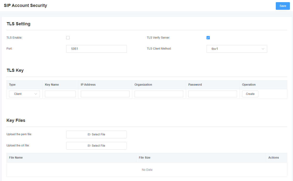
Table 4-5-1 Instruction of TLS
| Options | Definition |
| TLS Enable | Enable or disable DTLS-SRTP support. |
| TLS Verify Server | Enable or disable TLS verify server (default is no). |
| Port | Specify the port for remote connection. |
| TLS Client Method | Values include tlsv1, sslv3, sslv2, specify protocol for outbound client connections (default is sslv2). |
5. Routing
The gateway has a friendly user interface and very flexible settings. It supports up to 512 routing rules and each routing rule supports up to 100 pairs of calling/called number filtering and conversion operations. It supports DID function (the use of DID function: how to use the T1/E1 gateway DID function of China Telecom). The gateway supports trunk group and trunk priority management.
5.1 Call Routing Rules
Figure 5-1-1 Routing Rules

Click “Add” , you can set up a new routing rule. Click “Edit” to modify the routing rule, and click “Delete” to delete the routing rule.
Figure 5-1-2 Example of Setup Routing Rule

Table 5-1-1 Definition of Call Routing Rule
| Options | Definition |
| Routing Name | This is a rule name. The type of match usually used to describe (for example, ‘sip1 TO port1′ or ‘port1 TO sip1′). |
| Call Is From | Source of the call. |
| Call Delivery | The destination to receive the incoming calls. |
| DISA Timeout | The specific setting time of DISA timeout. |
| Maximum Number of Digits In Password | Set the maximum number of password digits |
| Password | Set a password within the specified range |
Figure 5-1-3 Advance Routing Rule
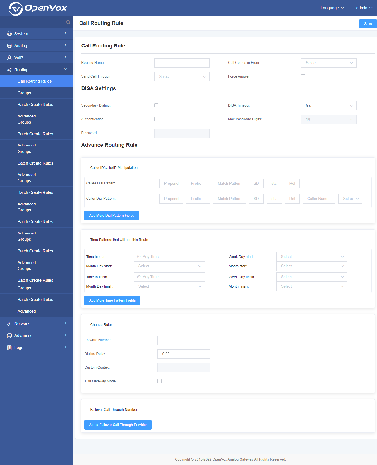
Table 5-1-2 Definition of Advanced Routing Rule
| Options | Definition |
| CalleeID/callerID Manipulation | A Dial Pattern is a unique set of digits that will select this route and send the call to the designated trunks. If a dialed pattern matches this route, no subsequent routes will be tried. If Time Groups are enabled, subsequent routes will be checked for matches outside of the designated time(s).
X matches any digit from 0-9 Z matches any digit from 1-9 N matches any digit from 2-9 [1237-9]matches any digit in the brackets (example: 1,2,3,7,8,9) *matches one or more digits Prepend<add prefix>: The number added when the pattern matches successfully. If the dialed number matches the pattern specified in the subsequent column, the number will be added before being sent to the trunk. Prefix: Removed when the pattern is matched successfully. The dialed number is matched with the pattern specified in the subsequent column. Once the match is successful, the prefix will be removed from the number before being sent to the trunk. Match Pattern: The dialed number will be compared with the number in the “prefix +” this matching pattern. Once the match is successful, the matched pattern part of the dial will be sent to the trunks. SDfR<Delete digits from the right>: The number of digits to be deleted from the right end of the number. If this value of this item exceeds the length of the current number, the entire number will be deleted. RDfR<Reserved digits from the right>: The reserved digits from the right. StA<Add Suffix>: Add this number from the right end of the current number. Caller Name <caller display name>: Set your favorite caller name before sending this call to the terminal, allowing the use of local languages, such as Chinese and Latin. |
| Time Patterns that will use this Route | Time mode setting of routing rules. |
| Forward Number | What destination number will you dial?
This is very useful when you have a transfer call. |
| Failover Call Through Number | The gateway will attempt to send the call by the order you specified. |
5.2 Groups
Sometimes you want to make a call through one port, but you don’t know if it is available, so you have to check which port is free. That would be troublesome. But with our product, you don’t need to worry about it. You can combine many Ports or SIP to groups. Then if you want to make a call, it will find available port automatically.
Figure 5-2-1 Group Rules

You can click the “Add” button to set up a new group, if you want to modify an existing group, you can click the “Edit” button.
Figure 5-2-2 Create a Group
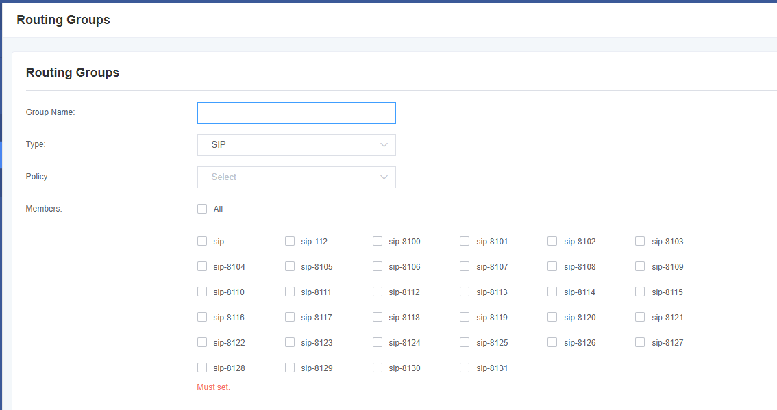
Figure 5-2-3 Modify a Group
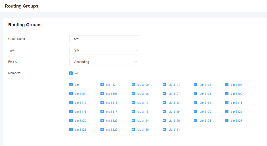
Table 5-2-1 Definition of Routing Groups
| Options | Definition |
| Group description | The name of the route, used to describe the type of this call route, for example, sip1 TO port1 or port1 TO sip2. |
5.3 Batch Create Rules
If you bind telephone for each FXO port and want to establish separate call routing for them. For convenience, you can create call routing rules for each FXO port at once in this page in batches.
Figure 5-3-1 Batch Create Rules

5.4 Advanced
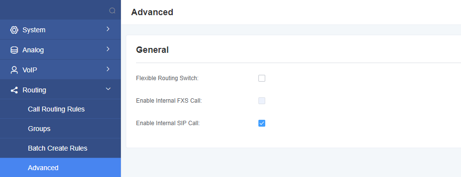
Figure 5-4-1 General
6. Network
On “Network” page, there are “Basic Settings”, “VPN Settings”, “DDNS Settings”, “Toolkit”, “Security Settings”, and “Security Rules”.
6.1 Basic Settings
There are three types of LAN port IP to choose from: Factory, Static and DHCP. The default type is: factory, the default IP is 172.16.99.1. If you forget the current IP, you can connect the phone to any FXS port of the analog gateway and dial “**” to query the current IP.
Figure 6-1-1 LAN Settings Interface
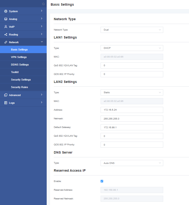
Table 6-1-1 Definition of Network Settings
| Options | Definition |
| Network Type | The name of network interface. |
| Type | The method to get IP.
Static: manually set up your gateway IP. DHCP: dynamically obtain the gateway IP address. |
| MAC | The physical address of the network interface. |
| Address | The IP address of your gateway. |
| Netmask | The subnet mask of your gateway. |
| Default Gateway | Default getaway IP address. |
| Reserved Access IP | List of domain name server IP addresses. This information is mainly obtained from the local network service provider. |
| Enable | Enable or disable the reserved IP address switch.
ON(enabled), OFF(disabled) |
| Reserved Address | The reserved IP address for this gateway. |
| Reserved Netmask | The subnet mask of the reserved IP address. |
6.2 VPN Settings
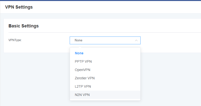
You can select VPN type and upload OpenVPN client configuration file or fill in PPTP VPN account information. If successful, you can see a VPN virtual network card on the system status page. You can refer to the parameter hints and sample configuration.
Figure 6-2-1 VPN Interface
6.3 DDNS Settings
You can enable or disable DDNS (Dynamic Domain Name Server) according to your needs
Figure 6-3-1 DDNS Interface
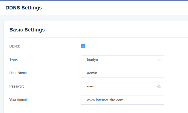
Table 6-3-1 Definition of DDNS Settings
| Options | Definition |
| DDNS | Enable/Disable DDNS(dynamic domain name server) |
| Type | Set the type of DDNS server. |
| Username | Your DDNS account’s login name. |
| Password | Your DDNS account’s password. |
| Your domain | The domain to which your web server will belong. |
6.4 Toolkit
This tool is used to detect the network connection, you can execute the Ping command on the web interface.
Figure 6-4-1 Network Connectivity Checking
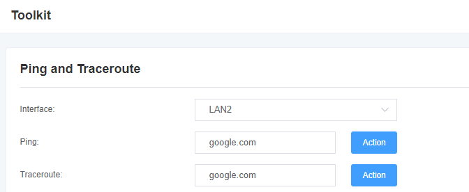
Figure 6-4-2 Channel Recording
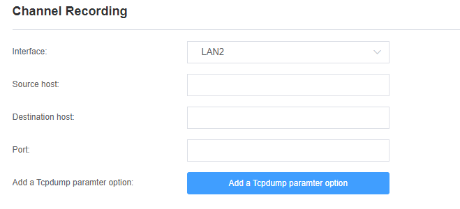
Figure 6-4-3 Capture Network Data
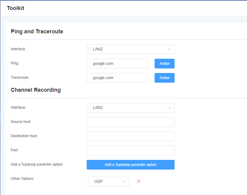
Table 6-4-1 Definition of Channel Recording
| Options | Definition |
| Interface | The name of network interface. |
| Source Host Address | Specify the source address of the data you want to get |
| Destination Host | Specify the destination address you want to get data from |
| Port | Specify the port where you want to get data |
| Channel | Specify the channel number you want to get data |
| Tcpdump Option Parameter | The tool of tcpdump capture network data by parameter option specified. |
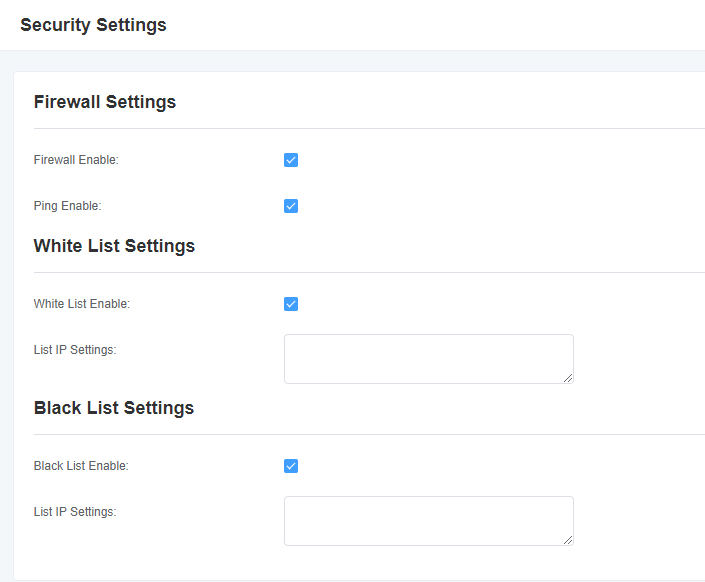
6.5 Security Settings
Figure 6-5-1 Security Settings Interface
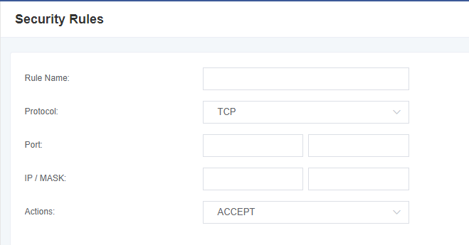
6.6 Security Rules
Figure 6-5-1 Security Settings Interface
7. Advanced
7.1 API
When you make “Enable” switch to “on”, this page is available.
Figure 7-1-1 API Interface
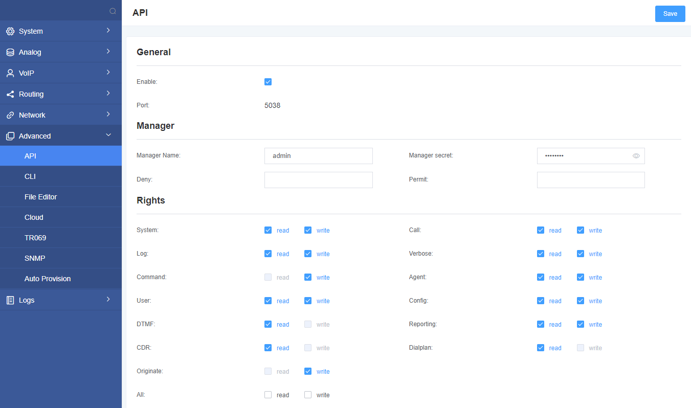
Table 7-1-1 Definition of Asterisk API
| Options | Definition |
| Port | Network port number |
| Manager Name | Name of the manager cannot contain spaces |
| Manager Secret | Password for the administrator.
Characters: Allowed characters “-_+.<>&0-9a-zA-Z”. Length: 4-32 characters. |
| Deny | If you want to deny some hosts or networks, use char & as separator. Example: 0.0.0.0/0.0.0.0 or 192.168.1.0/255.255.255.0&10.0.0.0/255.0.0.0 |
| Permit | If you want to permit many hosts or network, use char & as separator.Example: 0.0.0.0/0.0.0.0 or 192.168.1.0/255.255.255.0&10.0.0.0/255.0.0.0 |
| System | General information about the system and ability to run system management commands, such as Shutdown, Restart, and Reload. |
| Call | Channel information and setting information of the channel in use. |
| Log | Logging information. Read-only. (Defined but not yet used.) |
| Verbose | Verbose information. Read-only. (Defined but not yet used.) |
| Command | CLI commands allowed to run. (Read-only) |
| Agent | Information about queues and agents,and ability to add queue members to a queue. |
| User | Permission to send and receive UserEvent. |
| Config | Ability to read and write configuration files. |
| DTMF | Receive DTMF events. (Read-only) |
| Reporting | Ability to get information about the system. |
| CDR | Output of cdr, manager, if loaded. Read-only. |
| Dialplan | Receive NewExten and Varset events. Read-only. |
| Originate | Permission to originate new calls. Write-only. |
| All | Select all or deselect all. |
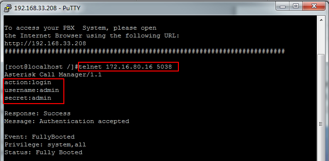
Refer to the above configuration diagram, the host 172.16.80.16/255.255.0.0 has been allowed to enter the gateway API, and the port number is 5038.
Figure 7-1-2 Putty Display Image
7.2 CLI
In this page, you are allowed to run Asterisk commands.
Figure 7-2-1 Asterisk Command Interface
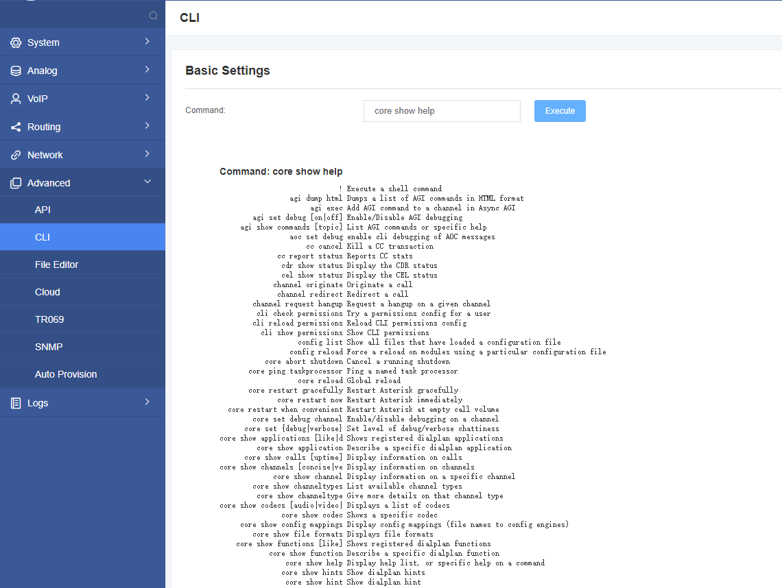
For example: enter “help” or “?” in the command bar, after execution, the page will prompt for executable commands, as shown in the figure above.
7.3 File Editor
On this page, you are allowed to edit and create configuration files.
Figure 7-3-1 Configuration Files List
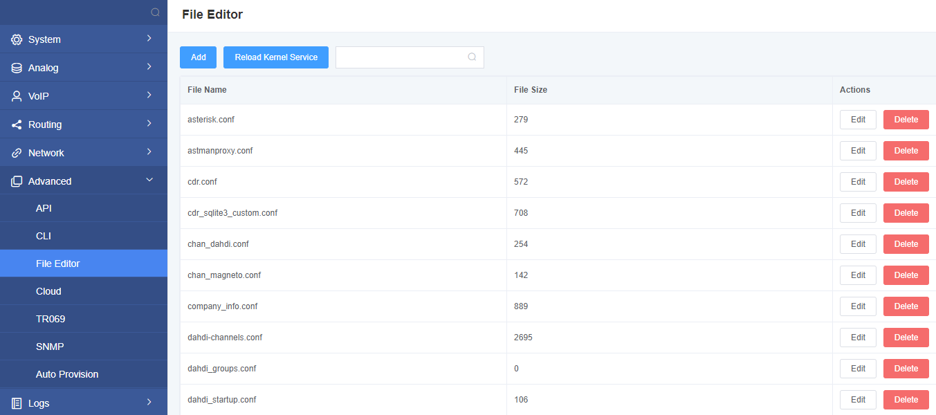
Notice: After modifying the configuration file, Asterisk needs to be reloaded.
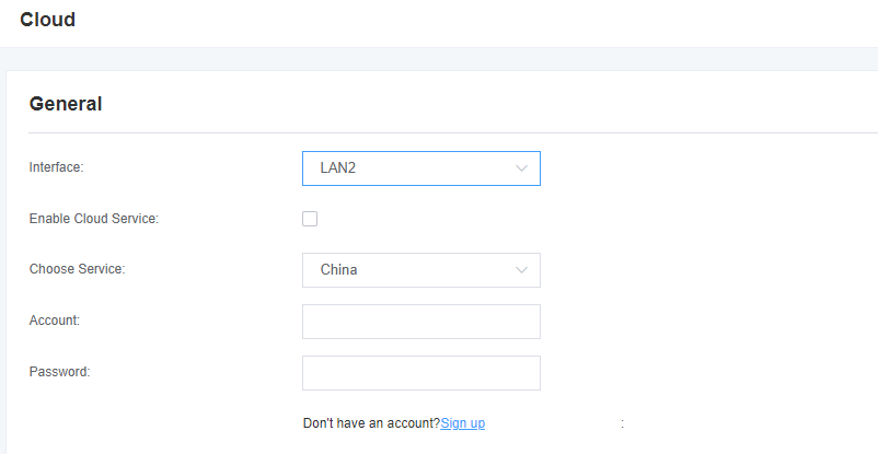
7.4 Cloud Management
Figure 7-4-1 Cloud Management Interface
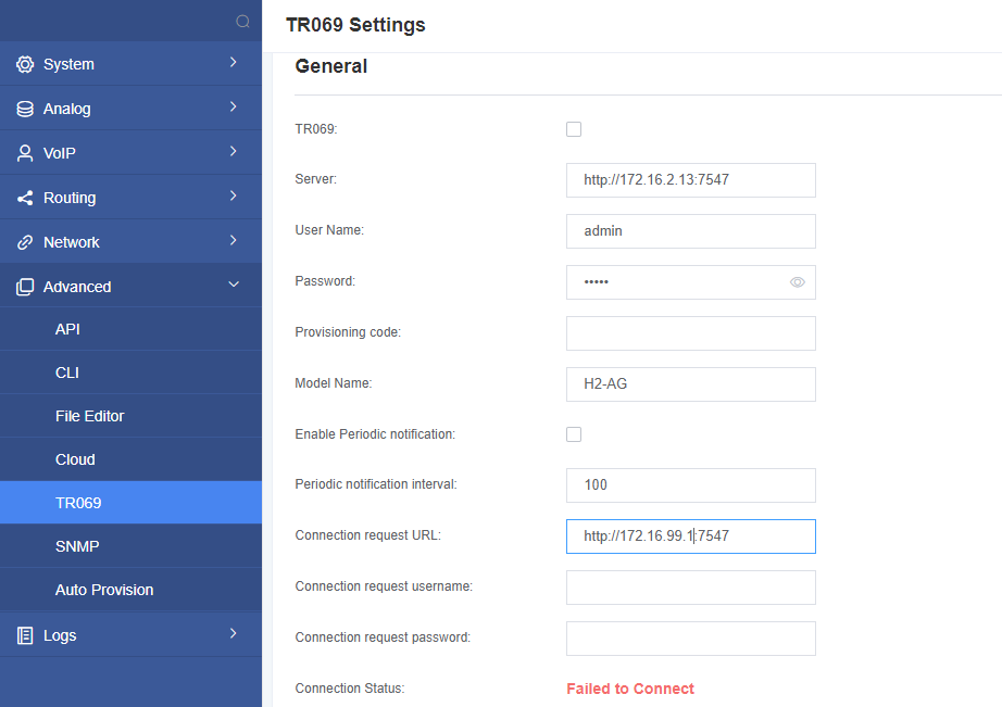
7.5 TR069
Figure 7-5-1 TR069 Interface
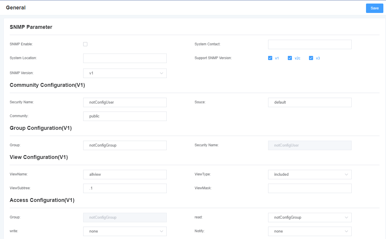
7.6 SNMP
Figure 7-6-1 SNMP Interface
7.7 Auto Provision Settings
Figure 7-7-1 Auto Provision Settings

8. Logs
8.1 Log Settings
In the log setting interface, open the corresponding log option, and you can view different logs in the corresponding interface. Take the system log as an example.
Figure 8-1-1 Logs Settings
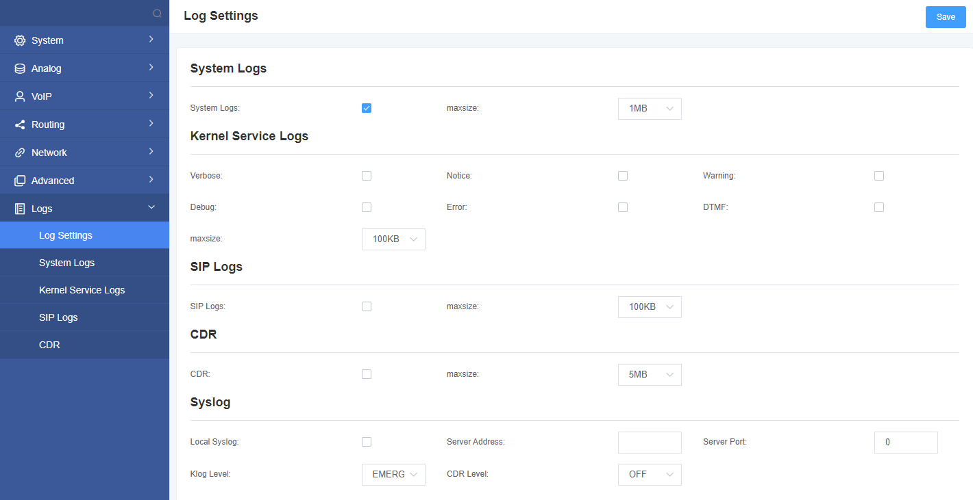
Figure 8-1-2 System Log Output
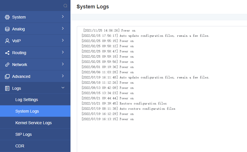
Table 8-1-1 Definition of Log Option
| Options | Definition |
| System Logs | Whether to open the system log. |
| Auto clean
(System Logs) |
switch on :
when the size of log file reaches the max size, the system will cut a half of the file. New logs will be retained. switch off : logs will remain, and the file size will increase gradually. default on, max size=1MB. |
| Verbose | Asterisk console verbose message switch. |
| Notice | Asterisk console notice message switch. |
| Warning | Asterisk console warning message switch. |
| Debug | Asterisk console debug message switch. |
| Error | Asterisk console error message switch. |
| DTMF | Asterisk console DTMF info switch. |
| Auto clean:
(asterisk logs) |
switch on:
when the size of log file reaches the max size, the system will cut a half of the file. New logs will be retained. switch off : logs will remain, and the file size will increase gradually. default on, max size=100KB. |
| SIP Logs: | Whether enable or disable SIP log. |
| Auto clean:
(SIP logs) |
switch on :
when the size of log file reaches the max size,the system will cut a half of the file. New logs will be retained. switch off : logs will remain, and the file size will increase gradually. default on, default size=100KB. |
8.2 CDR
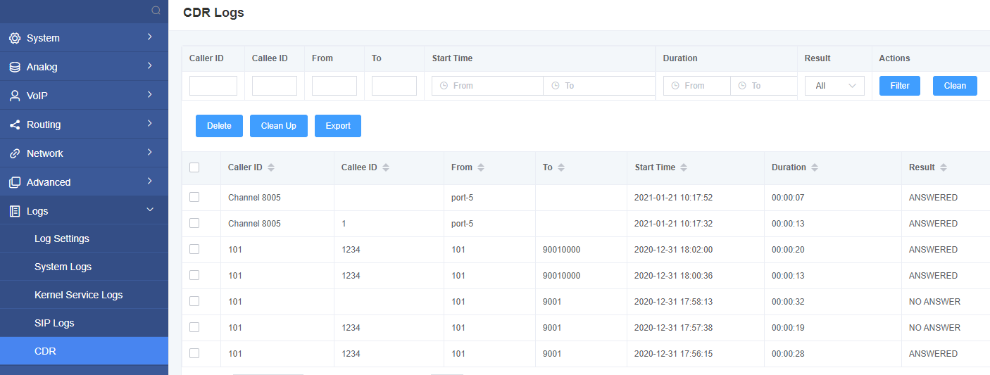
You can browse the details of each call record on this page. If you need to search for a specific record, you can use the filter function.
Figure 8-2-1 Call Detail Record
