MAG1100 Analog Gateway Quick Installation Guide
OVERVIEW
OpenVox MAG1100 is a multifunctional analog gateway for seamless connection between IPPBX, fax machines, analog phones, and operators. It provides four interfaces of RJ21, covering almost all the wiring needs of users in all scenarios. In addition, it has excellent full concurrent voice/ fax processing capabilities, strong performance, and high stability, and provides high-quality call services for operators, enterprises, call centers, and residential users in residential communities.
Precautions:
- Do not attempt to open, disassemble, or modify the device.
- Do not expose this device to temperatures outside the range of Operation: 0°C to 50°C / Storage: -20°C to 60°C.
- Do not expose the device to environments outside of the following humidity range: 10% to 90% Non-condensing.
- Do not power cycle the Analog IP Gateway during system boot up or firmware upgrade. You may corrupt firmware images and cause the unit to malfunction.
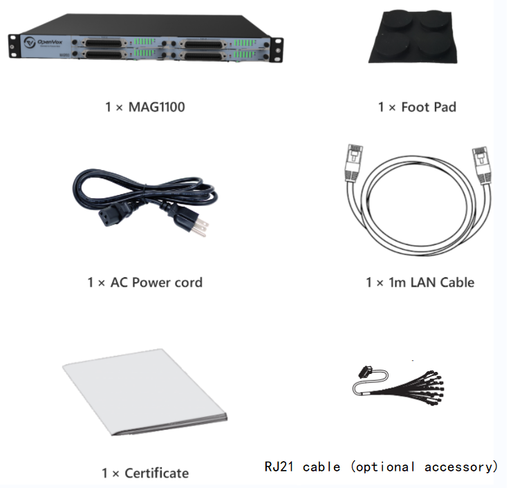
PACKAGE CONTENTS

MAG1100 PORTS
1:Power status indicator
2:Running status indicator
3:Channel status indicator
4:RJ21 ports

1:RST button
2:Console port
3:MGMT/Lan2 port
4:WAN/Lan1 port
5:SFP port
6:Power switch
CONNECTING THE MAG1100
The MAG1100 is designed for easy configuration and easy installation. To connect the MAG1100, please follow the steps above:
1. Connect a standard touch-tone analog telephone (or fax machine) to the FXS analog port (MAG1100 has no FXS port, and it needs to use the RJ21 telco cable to connect the RJ21 port on its back panel, see section “Telecom Port Installation “ for details).
2. Plug the Ethernet cable into the wan port of the MAG1100 and connect the other end of the Ethernet cable to an uplink port (a router or a modem, etc.)
3. Plug the power adapter into the MAG1100 and connect it to a wall outlet.
4. When the phone adapter is ready for use, the Power, Ethernet, and phone LEDs will be solidly lit.
CONFIGURING THE MAG1100
The MAG1100 can be configured either through the PC’s Web browser using the embedded Web GUI .
Obtaining the IP address
You also can refer to the following steps to obtain an IP address.
1. Using an analog phone, connect to any of the phone ports.
2. Press *02 will announce the current IP address. The default is to broadcast the IP in English.
Configure by Web GUI
Via Lan2 port
Connect MAG1100 through LAN2 port, please refer to the following steps.
1. Power your MAG1100 with the correct size AC/DC.
2. Open a web browser on your computer.
3. Enter the IP address of LAN2 port (default IP : 192.168.100.1 subnet mask:255.255.255.0) into the address bar of your browser.
4. Enter the administrator password to access the Web Configuration Menu. (By default, the administrator user name and password are admin).
Note: The computer must be connected to the same subnet as the MAG1100. This can easily be done by connecting the computer to the same hub or switch as the MAG1100.
TELECOM PORT INSTALLATION
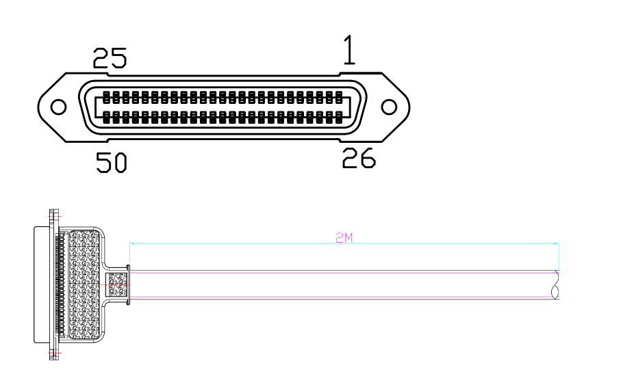
MAG1100 uses a 50-pin RJ21 Telco Amphenol port as an alternative interface (For mag1100, the telco port is mandatory) for connection to analog devices, such as analog telephones or fax machines. When installing the telco port, a common RJ21 Telco Amphenol 50 pin 25 pair cable is needed (included in the MAG1100 package only).You can connect the cable to an RJ11 patch panel, which could provide better cable management in most scenarios. Meanwhile, MAG1100 also adapts RJ45, if you use RJ45, please refer to RJ45 wire sequence
Below is a picture of an RJ21 port:

The following table shows the correspondent relation between the No. of each Telco cable’s RJ11 crystal head and the real FXS port number of MAG1100.
| color | Tip | Ring | Color | FXS port |
| blue | 26 | 1 | white | port 1 |
| orange | 27 | 2 | white | port 2 |
| green | 28 | 3 | white | port 3 |
| brown | 29 | 4 | white | port 4 |
| grey | 30 | 5 | white | port 5 |
| blue | 31 | 6 | red | port 6 |
| orange | 32 | 7 | red | port 7 |
| green | 33 | 8 | red | port 8 |
| brown | 34 | 9 | red | port 9 |
| grey | 35 | 10 | red | port 10 |
| blue | 36 | 11 | black | port 11 |
| orange | 37 | 12 | black | port 12 |
| green | 38 | 13 | black | port 13 |
| brown | 39 | 14 | black | port 14 |
| grey | 40 | 15 | black | port 15 |
| blue | 41 | 16 | yellow | port 16 |
| orange | 42 | 17 | yellow | port 17 |
| green | 43 | 18 | yellow | port 18 |
| brown | 44 | 19 | yellow | port 19 |
| grey | 45 | 20 | yellow | port 20 |
| blue | 46 | 21 | violet | port 21 |
| orange | 47 | 22 | violet | port 22 |
| green | 48 | 23 | violet | port 23 |
| brown | 49 | 24 | violet | port 24 |
Below is a picture of an RJ45 port:

RJ45 Cable Instruction:
| Channel | Pin | Tip/Ring |
| Channel 1
|
Pin 1 | Tip 1 |
| Pin 2 | Ring 1 | |
| Channel 2
|
Pin 3 | Tip 2 |
| Pin 4 | Ring 2 | |
| Channel 3
|
Pin 5 | Tip 3 |
| Pin 6 | Ring 3 | |
| Channel 4
|
Pin 7 | Tip 4 |
| Pin 8 | Ring 4 |
