How to Configure Self-Exchange
How to Configure Self-Switching
The OIAD version of self-switching can use one device as the master device, configure the extension information of all the devices on the master device, and the rest of the devices just need to click auto-synchronization on the self-switching page. Self-switching can be divided into two cases, one is self-switching with full S-port gateway and the other is self-switching with O-port gateway, and the following configuration is divided into two requirements.
Note: This self-swap feature is supported in version 2.2.7 and above.
Summary
The main highlight of OIAD self-switching is that you only need to configure all the extension information on the master device, and if there is any change, you can modify it on the master device, and the slave device only needs to synchronize it. When configuring self-switching, you need to know the IP and self-switching MAC address of the device, fill in the MAC of the slave device on the master device, and the slave device only needs to fill in the IP of the master device and click on the synchronization.There are two types of incoming calls to the O-port, one is a single extension ringing, and the other one is a group ringing, which can be cross-device ringing.
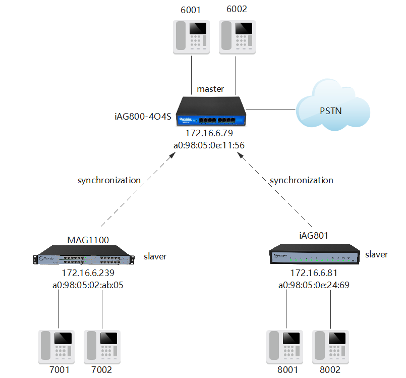
Scenario 1: Full S-port gateway configuration
Master device 172.16.6.79 configuration
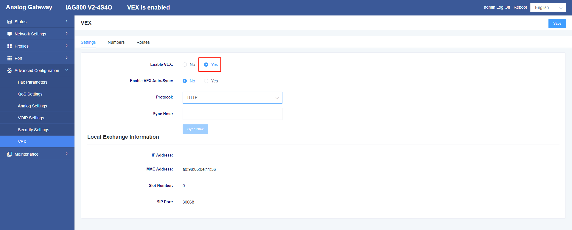
1.1 Enabling self-switching
Click Enable Self-Swap and save.
Figure 1 Self-exchange interface
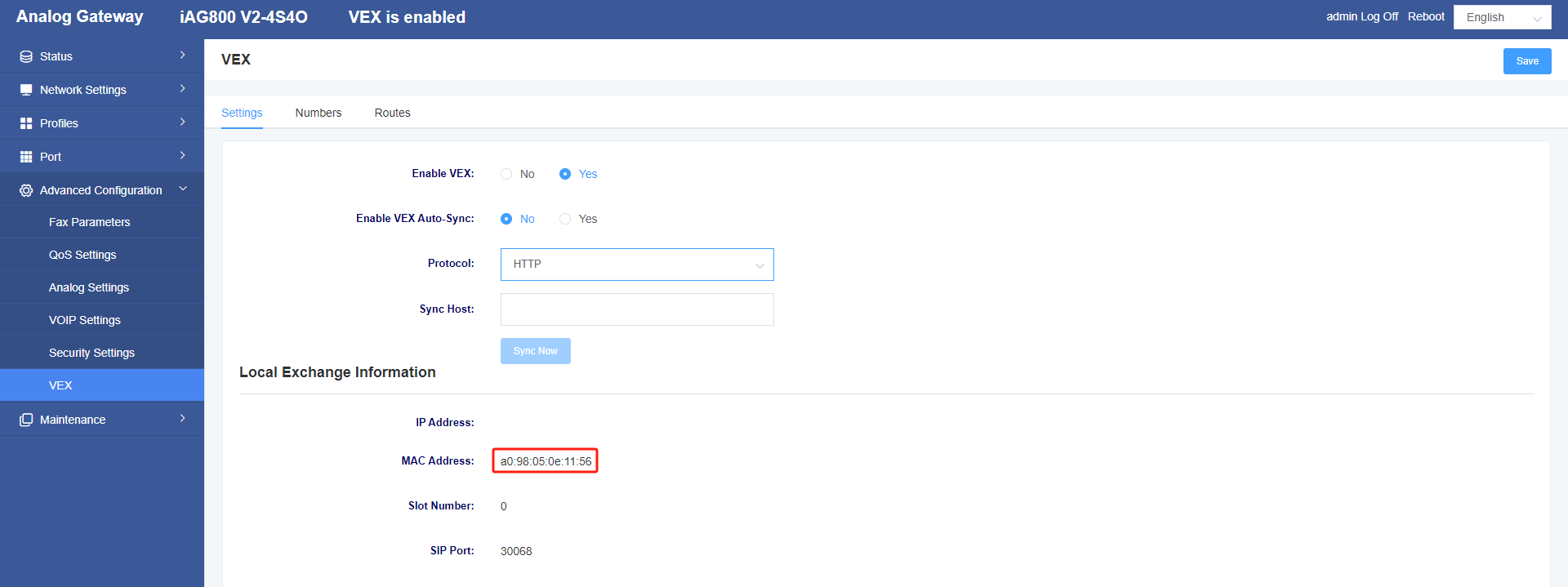
Note that the MAC address in the self-swap should be selected from the MAC address in the self-swap page.
Figure 2 Self-switching MAC address
1.2 Configure the numbering and routing tables for all devices
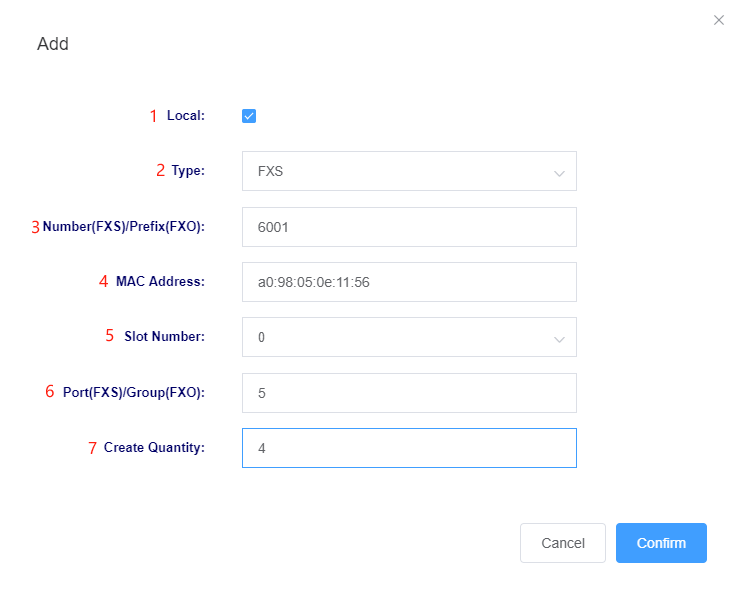
On the Self-Switching page of the master device 172.16.6.79 click on the number table, click on Add, and configure the extension number.
Figure 3 Numbering Table Screen

Parameter Description:
1: If you want to configure the extension number of this unit, you have to check this unit first.
2: Select to configure FXS or FXO.
3: The number is the starting extension number, or the prefix if you are configuring the FXO type.
4: MAC address is the MAC address of the device to be configured, and the MAC address does not need to be filled in when the local machine is checked.
5: For MAG1100, you need to pay attention to the slot number, and you need to know which slot is configured, while the rest of the series has the default slot number.
6: The port number is the starting number of the corresponding port you configured, this device is 5-8 for FXS ports, so fill in 5, if it is FXO type then it is fill in the FXO group number.
7: Creating a quantity of 4 is a sequential addition of one to the starting extension number.
Figure 4 Adding a master device number
To create the extension numbers for the rest of the devices, refer to the description above.
Note: The device slot number of the MAG1100, no matter how many, the port number starts from 1 and will not be cumulative.
Figure 5 Adding a slave device MAG1100 number
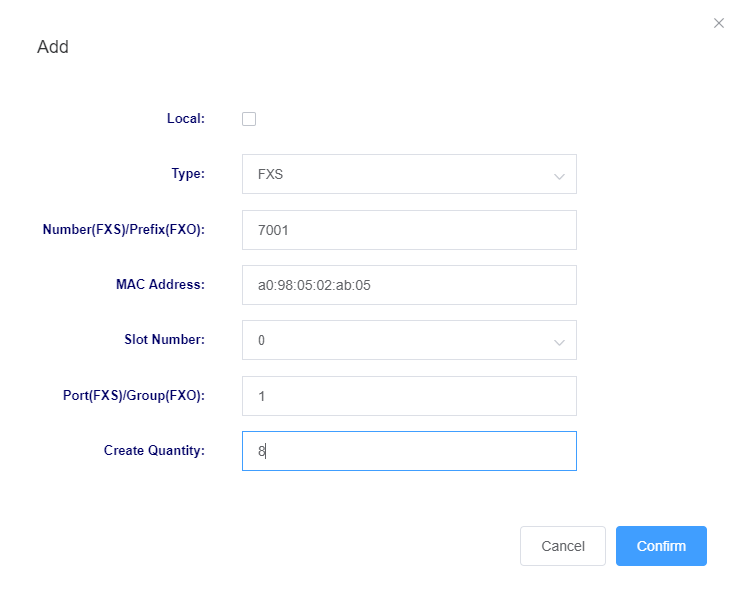
Figure 6 Adding a slave device iAG801 number
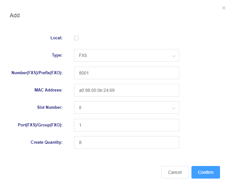
When you are finished creating extensions, click Save and then click Auto Generate in the routing table.
Figure 7 Master Device Number Table Screen
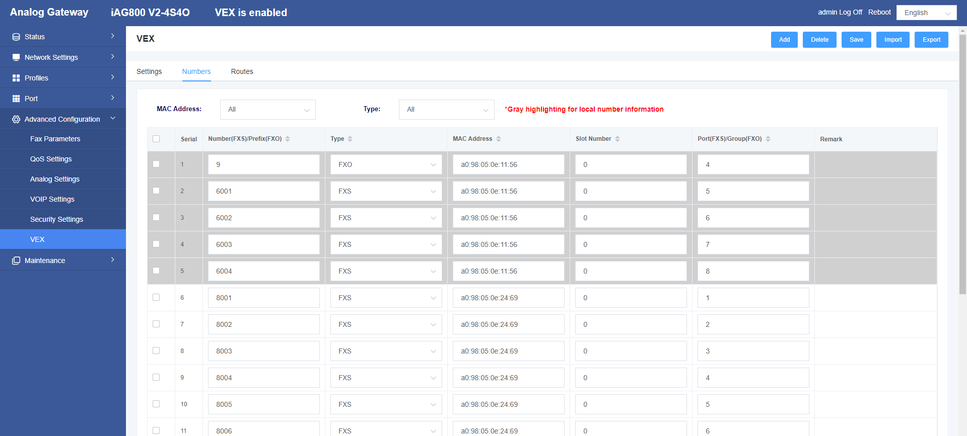
Figure 8 Master device routing table interface

2. From equipment configuration
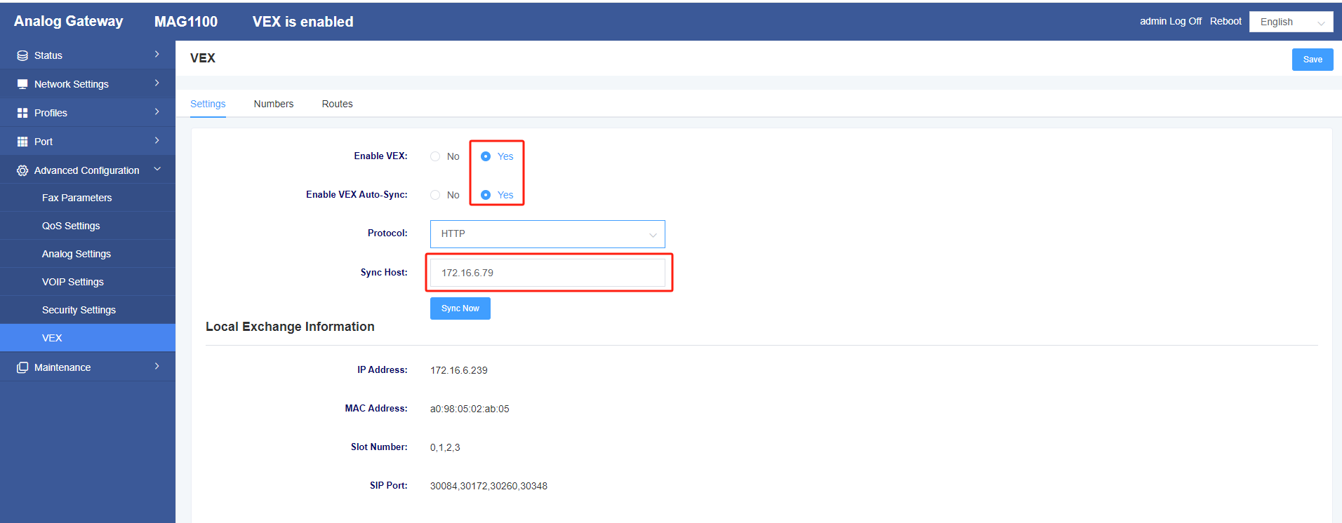
In the self-switching page of the two slave devices, click Enable self-switching and auto-synchronization, fill in the IP of the master device 172.16.6.79 for the synchronization address, then click Save, and finally click Auto-synchronization.
Figure 9 Slave device self-switching interface
3. Verification
After the synchronization is completed, inter-calls are made between any two different ports according to the numbering table.
Figure 10 Slave Device Number Table Screen
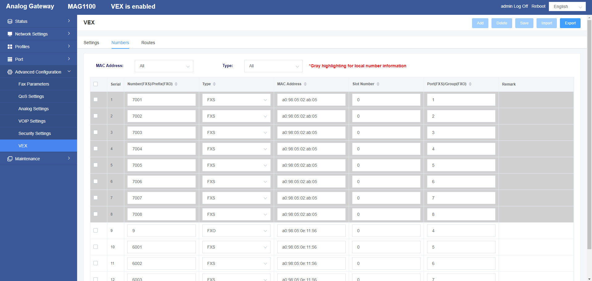
Figure 11 Slave device routing table interface

Scenario 2: Self-Switching Configuration with O-Ports
The S port is configured the same as scenario one, and the following is only about the configuration of the O port. Because the O port of this configuration is on the master device, configure the O port related configuration on the master device. If the O port is on the slave device, you need to configure the self-switching callout of the O port on the master device, and then configure the FXO/FXS port settings of the slave device, and finally click Synchronize in the slave device.
1.Configuring FXO Port Inbound
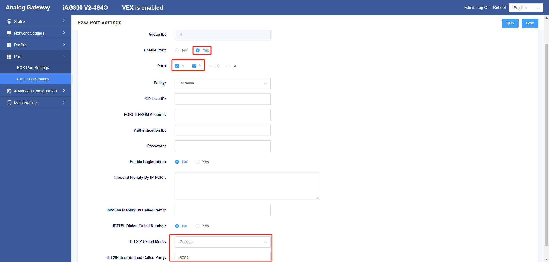
In the FXO port settings to add a port group, you can choose a port as a group or multiple ports as a group, check the box to enable, TEL2IP called mode select custom, TEL2IP custom called to select the O-port inbound call in the device you want to call, here you can fill in the extension number to be called, and finally click Save.
Figure 12 FXO Port Setting Screen
If you want to make several ports ring together, you need to configure it as follows.
Because the inbound caller is set to be 6002 corresponding to FXS6 port, I want to ring 6001 (that is, FXS5 port) together, I need to disable these functions of the corresponding ports, and then fill in PORT/5&&PORT/6 in the Unconditional Transfer section, so that when the caller from the O-port calls in, the extensions of 6001 and 6002 will ring at the same time.
Note: Currently this grouping can only exist in the same device.
Figure 13 FXS Port Call Setup Screen

If you need to cycle the ringing of several idle ports, you need to configure it as follows.
Fill in 40 for the group number in the Basic Settings of FXS Port Settings to disable these functions of the corresponding port, and fill in PORT+Ringing Policy+Group Number in Unconditional Transfer, for example, PORT/g40.
Figure 14 FXS Port Basic Settings Screen

Figure 15 FXS Port Call Setup Screen

An explanation of the ringing strategy g/G/r/R.
g: each time the first available channel in the group is selected to ring (from low to high)
G: Select the first available channel ringing in the group each time (from high to low)
r: Starts ringing each time from the position where it was last answered (lowest to highest).
R: Rings from the last answered position each time (highest to lowest)
2. Configuring FXO Self-Switched Outbound
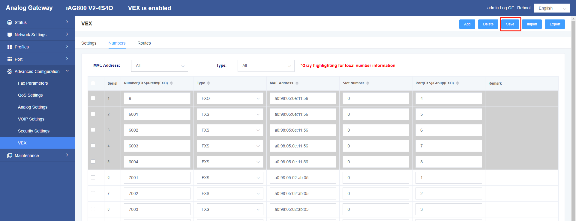
Click Add in the self-switched number table, select the FXO type, configure 9 as the outbound prefix, and finally click Save and click Synchronize Now in the remaining slave devices.
Figure 16 Add FXO Group Screen
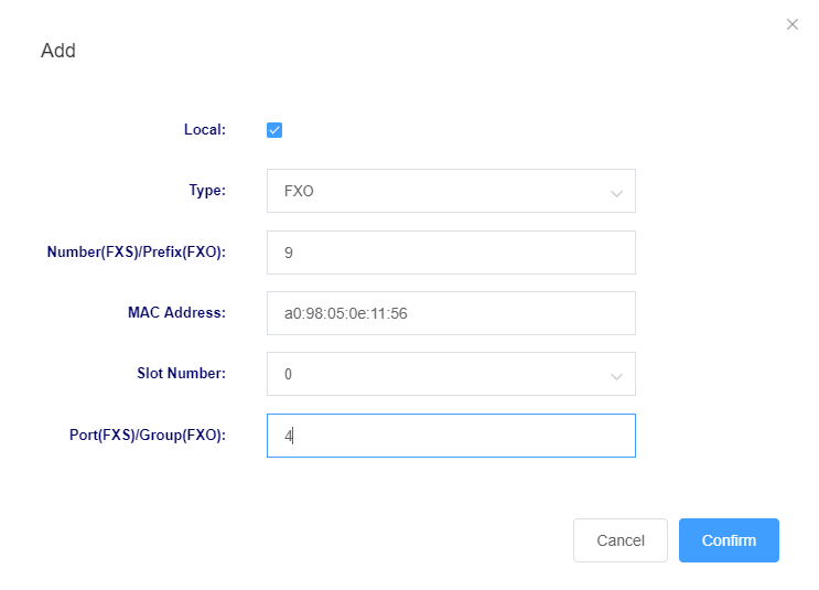
Figure 17 Master Device Configuration Completion Screen
3. Verification
After all devices have been synchronized, an analog phone on any of the S ports can make an outgoing call by dialing the 9+ phone number; a cellular phone can make the 6002 extension ring or the same group of extensions as the 6002 ring by dialing the outgoing number on the O port.
