iAG801 Analog Gateway User Manual
iAG801 Analog Gateway User Manual
1. Overview
1.1 Product introduction
OpenVox iAG801 is a multifunctional analog gateway that provides 8 FXS ports for seamless connection between IPPBX, fax machines, analog phones and operators. In addition, it has excellent full concurrent voice/fax processing capabilities, strong performance and high stability, and provides high-quality call services for operators, enterprises, call centers and residential users in residential communities.
The iAG801 Analog Gateway, a cost-effective product of the iAG Series, is an ideal analog VoIP gateway solution for SMBs and SOHOs. With friendly GUI and unique design, users may easily customize and configure their gateway. In addition, we have a complete API interface.
The iAG801 Analog Gateway is developed for interconnecting a wide selection of codecs including G.711A/U,G.723.1,G.729A,G.722,iLBC,OPUS,AMR and AMR-WB. iAG801 series use standard SIP protocol and compatible with leading VoIP platform, IPPBX and SIP servers, such as Asterisk, Issabel, 3CX, FreeSWITCH, BroadSoft and VOS VoIP operating platform.
1.2 Simple applications
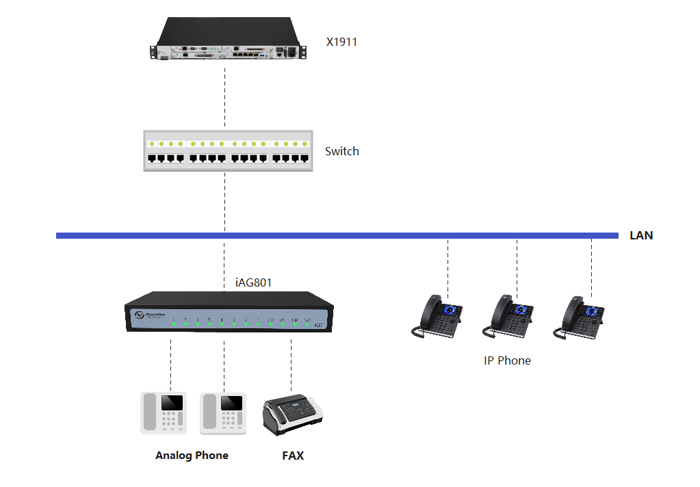
A simple application of the analogue web relation column is shown to you in Figure 1-2-1.
Figure 1-2-1 Application Topology Diagram
1.3 Product appearance
Figure 1-3-1 Product Appearance
Figure 1-3-2 Front Panel
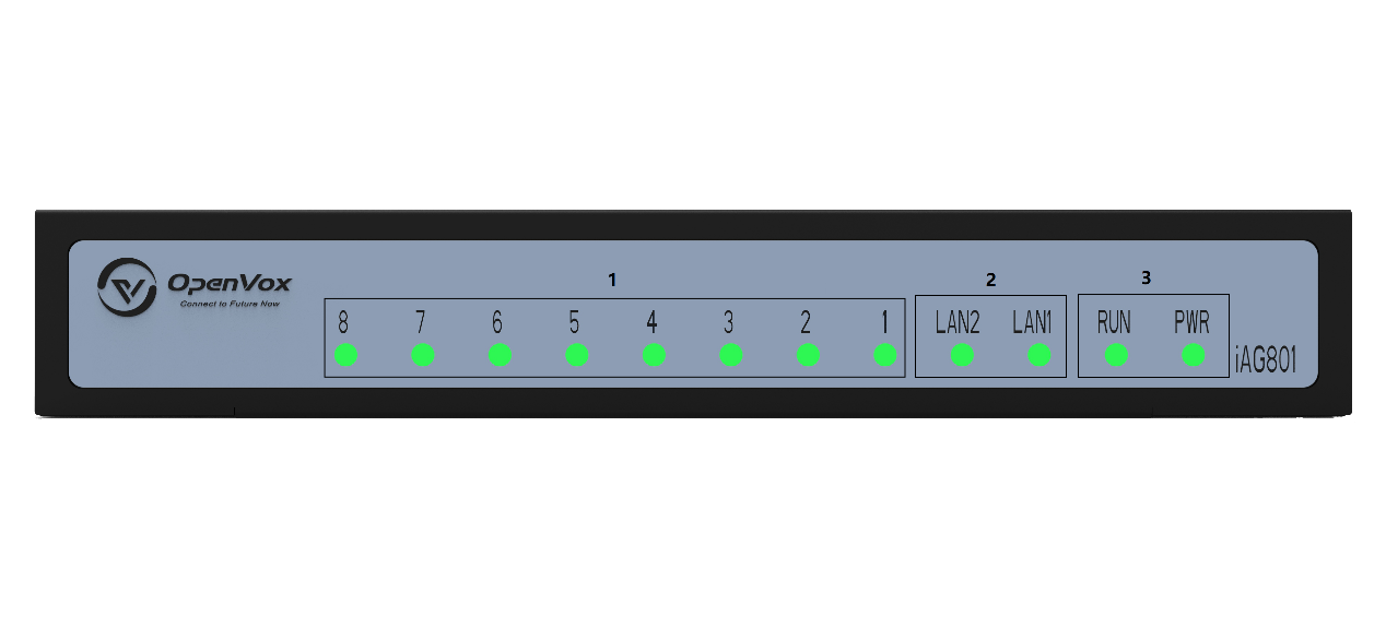
1: Module board power, operation status indicators
2: Analogue interface and analogue channel status indicators
Figure 1-3-3 Rear Panel
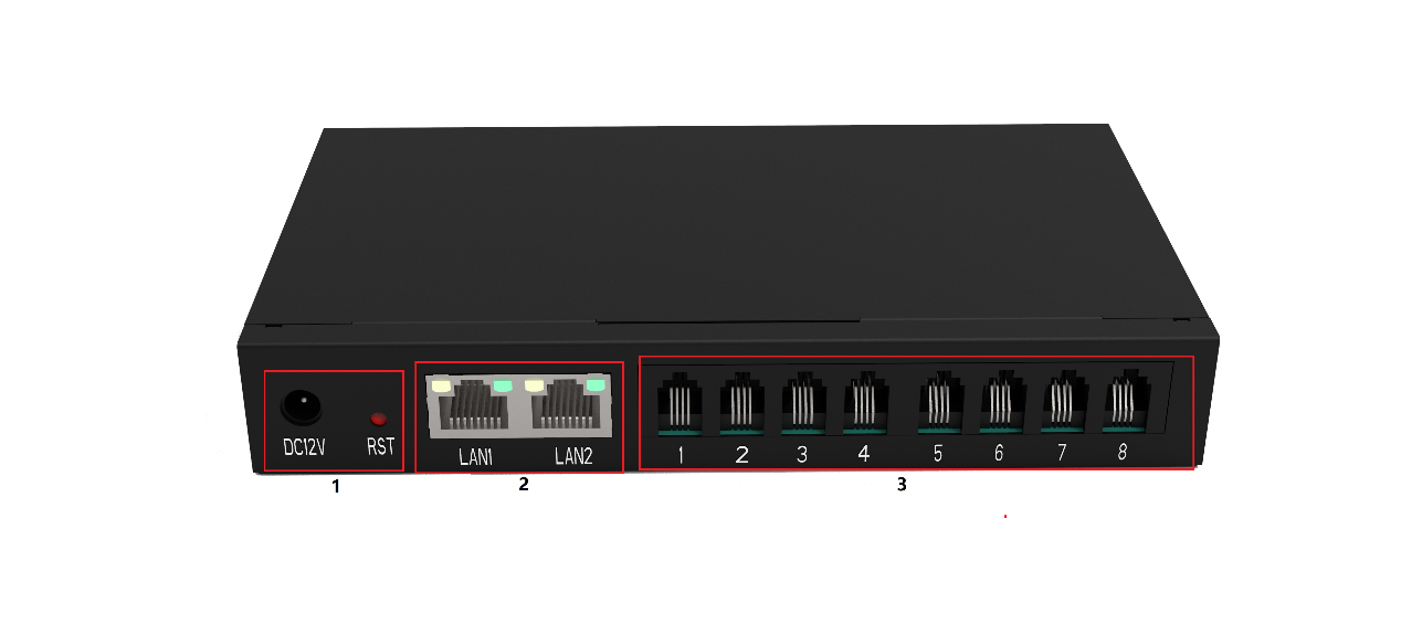
1 : Equipment power supply
2 : Device Reset Button
3 : Network port
1.4 Software features
| iAG801 | |
|---|---|
| telephone port | 8 FXS ports |
| Accounts and Templates | 8 FXS ports a SIP account Four templates |
| speech compression | G.711A/U,G.723.1,G.729A,G.722,iLBC,OPUS,AMR and AMR-WB |
| telex | T.38 complies with Class III fax relays up to 14.4kpbs and automatically converts to G.711 for fax transmission.T.38 fax relays use V.17, V.21, V27ter, V29 fax data pumps. |
| QoS | Diffserve, ToS, 802.1 P/Q VLAN tagging |
| telephone function | Caller ID display or blocking, Call Waiting, Blind and Consultation Transfer, Call Forward, Do Not Disturb, Call Back, Paging, Message Waiting Indicator and Interval Tone, Auto Dialling, Flexible Dialling Rules |
| DTMF method | Flexible DTMF transmission, user audio interface, RFC2833 and/or SIP Info. |
| SIP signalling | SIP (RFC 3261) over UDP/TCP/TLS |
| safety | SRTP/TLS/SIPS, HTTPS, 802.1x |
| Upgrade and deployment | TFTP, HTTP, HTTPS |
| network protocol | TCP/UDP, RTP/RTCP, HTTP/HTTPS, ARP, ICMP, DNS, DHCP, NTP, TFTP, PPPoE, STUN |
1.5 Hardware Features
| iAG801 | |
|---|---|
| Port Type | RJ11/RJ45 |
| weights | 400g |
| sizes | 170mm x 98mm x 26mm |
| Power supply specifications | 12V 2A |
| maximum power | 12W |
| Operating temperature range | 0°C ~ 50°C |
| Storage environment humidity range | 10% ~ 90% non-condensing |
| Storage Ambient Temperature Range | -20°C ~ 70°C |
| accreditation | CE |
1.6 Software features
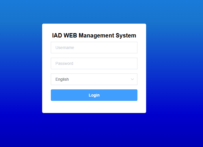
Default IP: 192.168.6.65
User name: admin
Password: admin
Connect the network cable to LAN1/LAN2 and enter the default IP in the browser to access the gateway for configuration.
Note: The default network mode of this product is bridge mode, no matter the network cable is connected to wan port or lan port, the IP address is the same.
Figure 1-3-1 Login Screen
2 Status
2.1 System Information
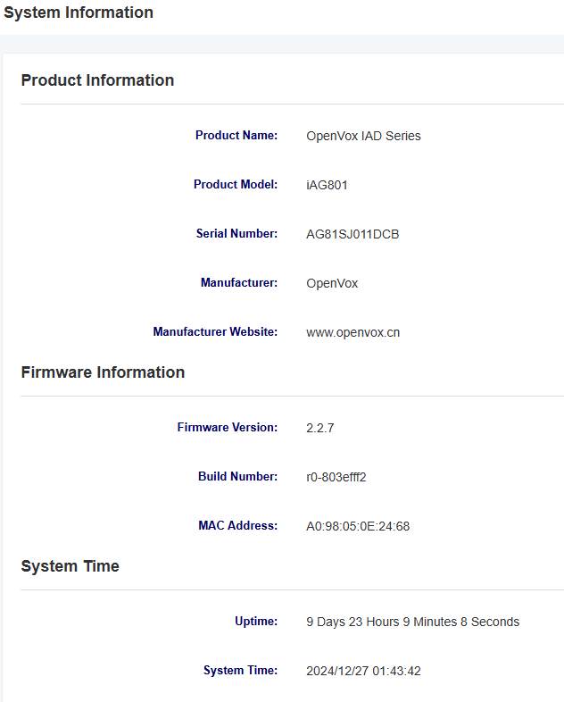
The System Status screen displays product information, firmware information, system time, and resource usage.
Figure 2-1-1 System Information Display
2.2 Network Status
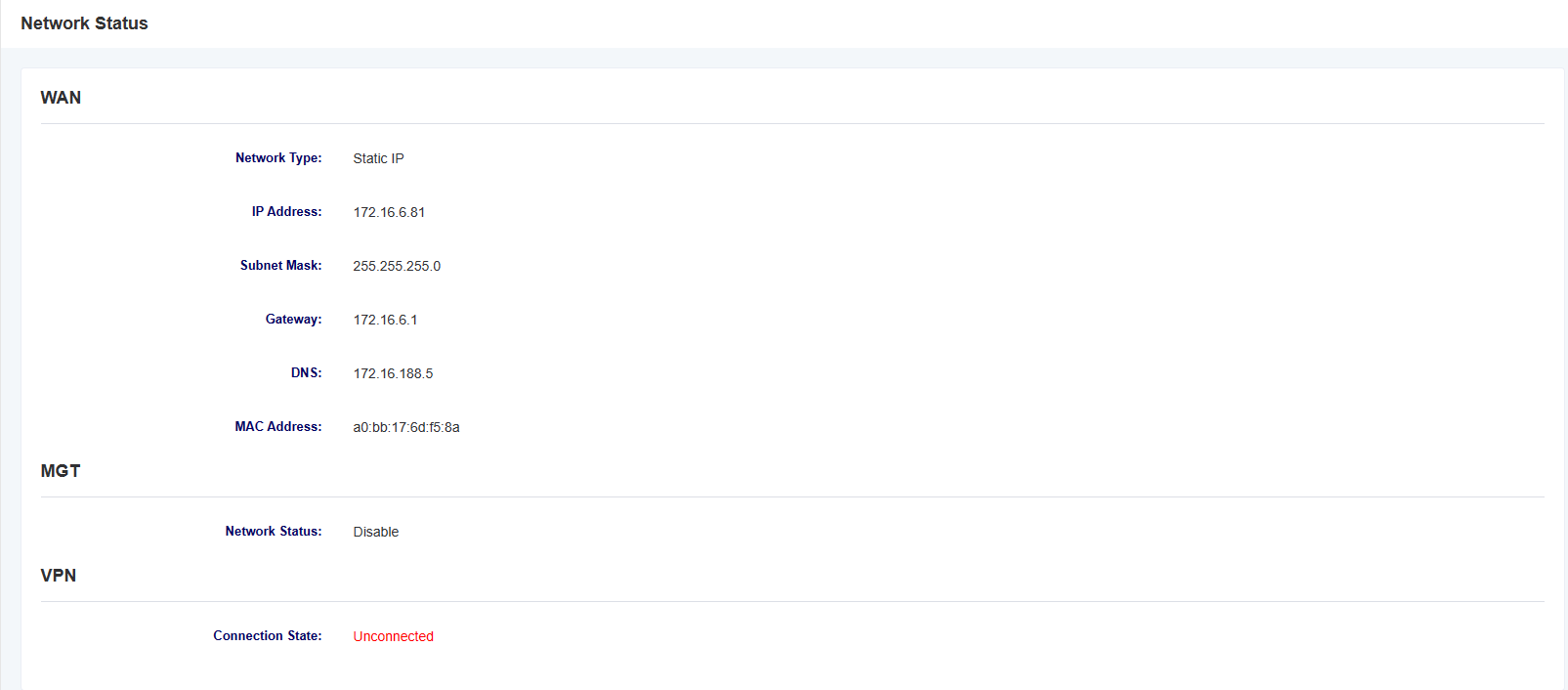
The Network Status screen displays the network status and VPN connection status.
Figure 2-2-1 Network Status
2.3 Port Status
In the “Port Status” page, the port type, enabled status, registered status, and off-hook status are displayed, and you can switch different interface boards by clicking the drop-down menu of the slot number.
Figure 2-3-1 Port Status

2.4 CDR
On the CDR page, users can set up CDRs and perform CDR queries
Figure 2-4-1 CDR
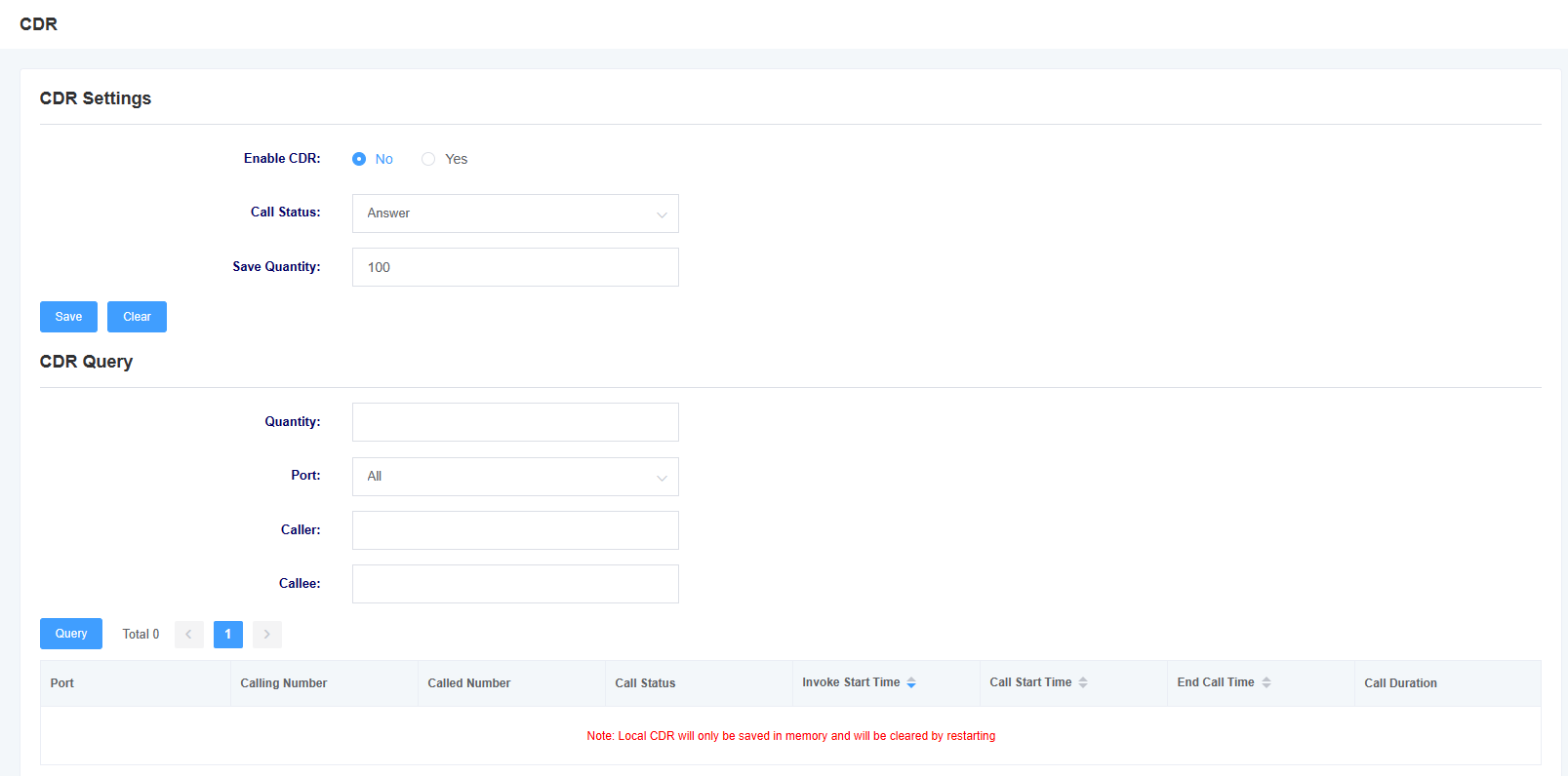
Note: CDRs are only stored in memory and will be cleared on reboot!
Table 2-4-1 CDR Options
| options | instructions |
| Enabling CDR | This option selects whether to enable CDR |
| Call Status | Selecting the status of calls saved by the CDR |
| Number of saves | Setting up CDR save entries |
| slot number | Select the slot number for the CDR query |
| quantities | Select the number of CDR queries |
| ports | Selecting the port for CDR queries |
| caller | Filter CDR enquiry items by calling number |
| called | Filter CDR enquiry items by called number |
2.5 Call Features Status
In the “Call Feature Status” page, it displays No Disturb Enable Status, Unconditional Transfer Status, and Busy Transfer Status, and you can switch different interface boards by clicking the drop-down menu of the slot number.
Figure 2-5-1 Call Features Status Screen

3. Network Settings
3.1 Local Network
Figure 3-1-1 Local Network Screen
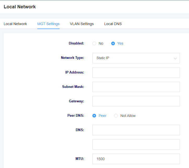
Table 3-1-1 Description of Local Network Interface Parameters
| options | instructions |
| Network Mode | Setting the network mode |
| Network type | Select network type: DHCP, Static IP, PPPoE |
| IP address | Setting the IP address of the device |
| subnet mask | Set the subnet mask of the device |
| default gateway | Setting the default gateway of the device |
| Primary DNS | Setting the device’s primary DNS |
| Secondary DNS | Setting the alternate DNS for the device |
| Management Access Options | Setting web login restrictions |
| Setting OPT 60 | Setting OPT 60 |
| MTU | set MTU |
Figure 3-1-2 MGT Setting Screen

Table 3-1-2 Description of MGT Setting Interface Parameters
| options | instructions |
| Network Mode | Setting the network mode |
| Network type | Select network type: DHCP, Static IP, PPPoE |
| IP address | Setting the IP address of the device |
| subnet mask | Set the subnet mask of the device |
| Gateway | Setting the gateway of the device |
| Peer DNS | Setting up a DNS Peering Connection |
| DNS | Setting the device’s DNS |
| MTU | set MTU |
Figure 3-1-3 VLAN Setting Screen
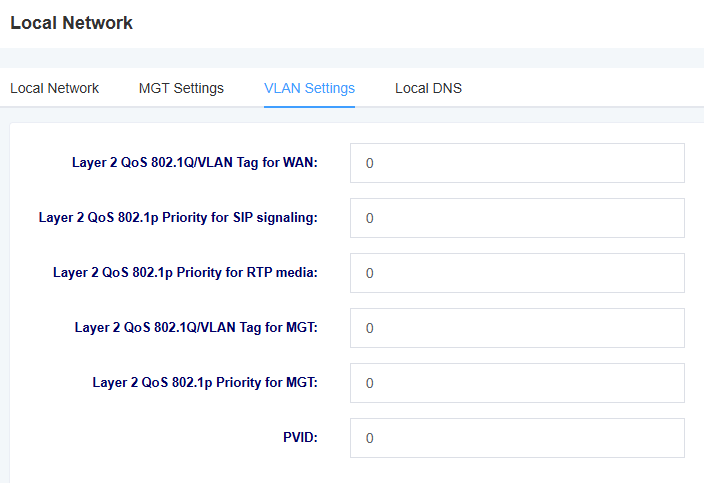
Table 3-1-3 Description of VLAN Setting Interface Parameters
| options | instructions |
| Layer 2 QoS 802.1Q/VLAN Tag for WAN | Setting the WAN tag |
| Layer 2 QoS 802.1p Priority for SIP signaling | Setting the SIP signaling priority |
| Layer 2 QoS 802.1p Priority for RTP media | Settings the RTP media priority |
| Layer 2 QoS 802.1Q/VLAN Tag for MGT | Setting the MGT Tag |
| Layer 2 QoS 802.1p Priority for MGT | Setting the MGT priority |
| PVID | setting the PVID |
Figure 3-1-4 Local DNS Screen

Figure 3-1-5 Add Local DNS Screen

Table 3-1-4 Description of Local DNS Setting Interface Parameters
| Options | Instructions |
| Domain | Settings the Domain |
| Parse IP | Set the IP to be resolved |
3.2 Static Routing
The Static Route screen displays the network interface, destination IP address, subnet mask, gateway, number of leaps, and operation of the static route. You can add a static route here. Click the Add button to add a static route.
Figure 3-2-1 Static Routing Interface

Figure 3-2-2 Add Static Routing Interface

3.3 Firewall
In the Firewall page, the name, protocol, source network domain, source IP, source port, destination network domain, destination IP, destination port, and rule action of the firewall rule are displayed. You can add firewall rules here to ensure the security of the device. Click the Delete button to delete a firewall rule, and click the Add button to add a firewall rule.
Figure 3-3-1 Firewall Interface

Figure 3-3-2 Add Firewall Rule Screen
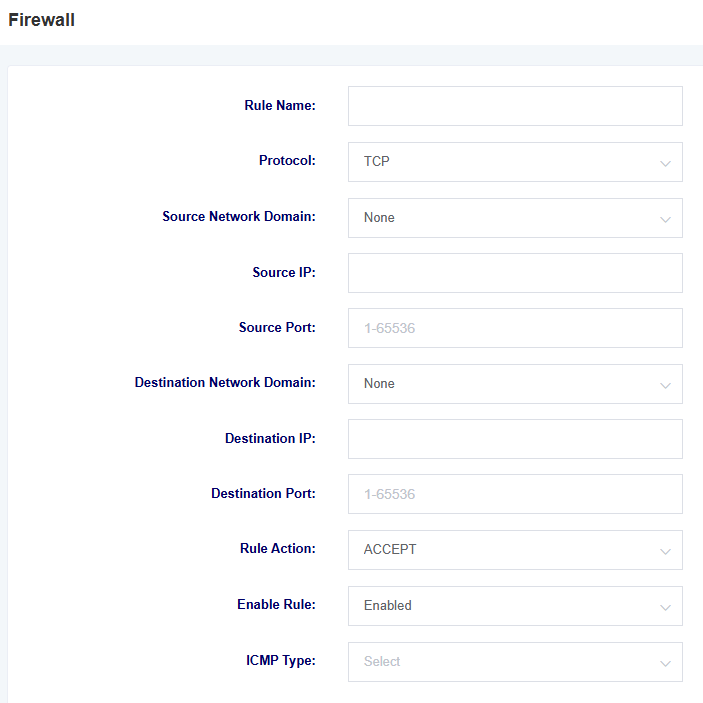
Table 3-3-1 Adding Firewall Rule Parameter Descriptions
| options | instructions |
| name | Name of the firewall rule |
| protocols | Protocols limited by firewall rules |
| source network domain | Source network domain for firewall rules |
| options | instructions |
| source IP | Source IP for firewall rule definition, or all IPs if left blank |
| source port | Defines the source port, in the range 1-65535 |
| target network domain | Target network domain for firewall rules |
| Target IP | Destination IP defined by firewall rule, or all IPs if left blank |
| target port | Define the destination port, in the range 1-65535 |
| Rules of the Road | Define the rule action, optional ACCEPT, REJECT, DROP |
| ICMP Type | Select ICMP Type |
3.4 IP Alias
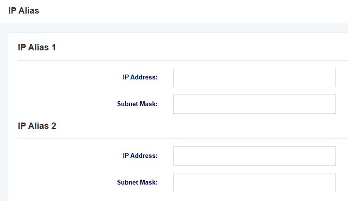
The iAG801 supports setting multiple IP addresses, which can be set in the IP Alias screen.
Figure 3-4-1 IP Alias Interface
3.5 VPN Settings
You can enable VPN and configure it in this interface. iAG1100 only supports Openvpn at the moment.
Figure 3-5-1 VPN Setting Interface

Table 3-5-1 VPN Setting Description
| options | instructions |
| VPN Type | Option to turn off VPN or use Openvpn |
| Account Authentication Name | Authentication name used by Openvpn |
| Account Authentication Password | Authentication password used by Openvpn |
| Cert Verify Password | Cert Verify Password |
| openvpn configuration contents | Uploading the openvpn configuration file |
| connection status | Display vpn connection status |
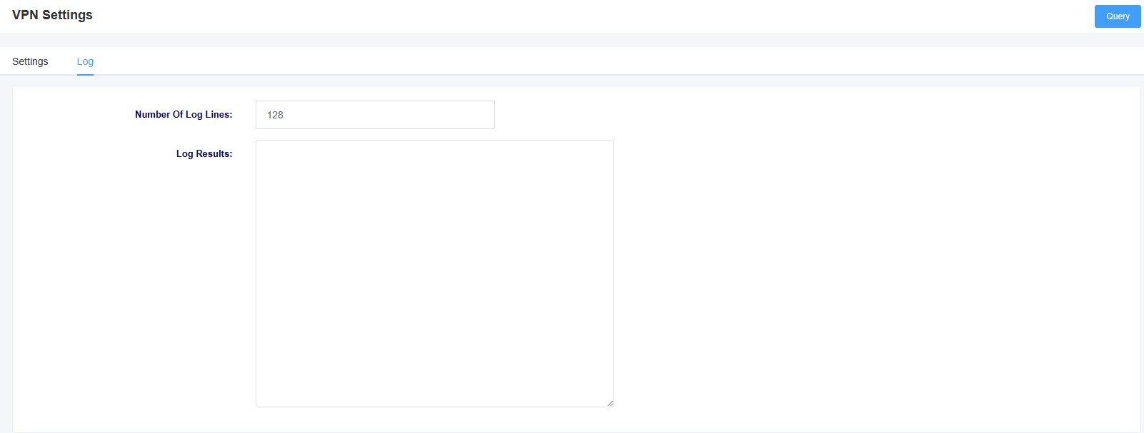
Under the Log page, you can select the number of rows to be displayed in the log, and then click the Query button. The log will be displayed in the Log Results box.
Figure 3-5-2 VPN Log Screen
4. Profiles
The iAG801 provides a convenient SIP registration method, which allows users to conveniently apply a set template to the FXS port, with a total of four templates available for setting.
4.1 SIP Settings
Figure 4-1-1 SIP Settings
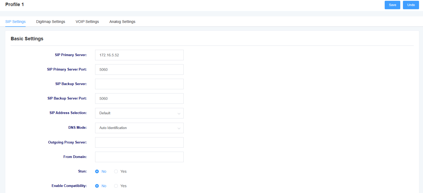
Table 4-1-1 Description of SIP Setting Parameters
| options | instructions |
| SIP Master Server | Setting up the SIP master server |
| SIP master service port | Setting up the SIP master server port |
| SIP standby server | Setting up a SIP standby server |
| options | instructions |
| SIP standby server port | Setting up the SIP standby server port |
| SIP address selection | Select which network port the SIP service is registered on |
| DNS mode | Set the DNS mode, optionally automatically or using DNSSRV |
| outgoing proxy server | By setting up an outbound proxy server, the gateway will send signaling to this external proxy instead of directly to the peer. |
| From Domain | Set the domain name to be used for the authentication counterpart |
| Stun | Select whether to enable the Stun service |
Figure 4-1-2 SIP Settings
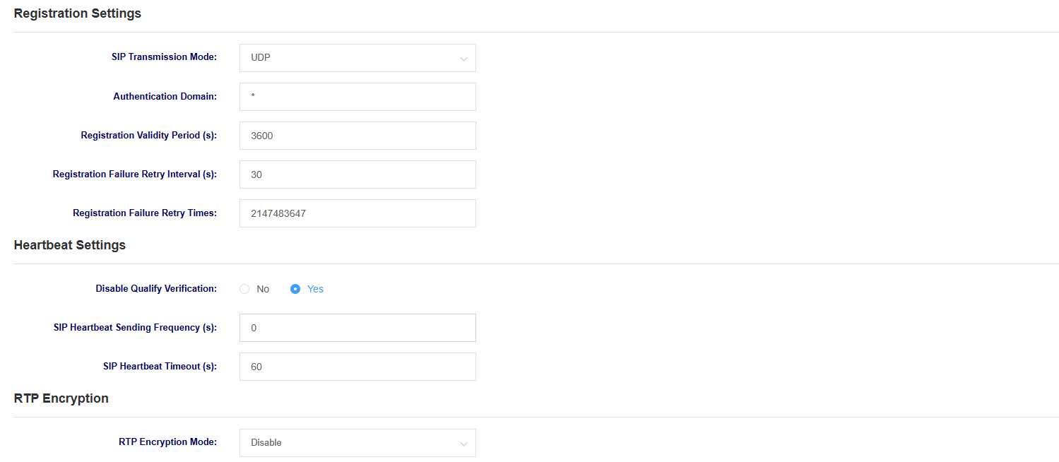
Table 4-1-2 SIP Setting Parameter Descriptions
| options | instructions |
| SIP transmission method | Set SIP transport mode, selectable UDP, TCP and TLS. |
| certification domain | Setting the SIP Registration Authentication Domain |
| options | instructions |
| Registration validity period | Set the registration validity period, default value is 3600 seconds |
| Registration Failure Retry Interval | Set the registration failure retry interval, the default value is 30 seconds |
| Number of failed registration retries | Set the number of failed registration retries, the default value is 2147483647 times |
| Qualify | Whether to enable qualify authentication |
| Sip heartbeat frequency | Setting the sip heartbeat packet sending frequency |
| Sip heartbeat timeout | Setting the sip heartbeat packet timeout |
| RTP encryption mode | Whether to enable RTP encryption |
Figure 4-1-3 SIP Settings
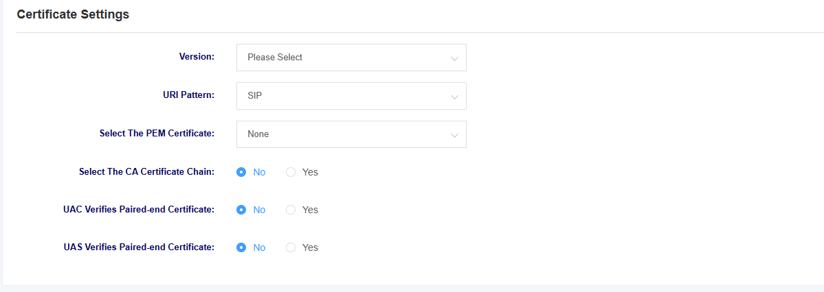
| options | instructions |
|---|---|
| Version | Select the version of the certificate, the device supports different versions of certificates for tls, ssl, ss |
| URI mode | Select URI mode, support SIP and SIPS |
| Select The PEM certificate | Select device PEM certificate |
| Select CA Certificate Chain | Select whether to enable CA certificate chain |
| options | instructions |
| UAC validates the counterpart’s certificate | As the calling party, select UAC to use the phone as the refresher. Or select UAS to use the called party or proxy server as the refresher. |
| UAS validates counterpart certificates | As the called party, select UAC to use the called party or proxy server as the refresher, or select UAS to use the phone as the refresher. |
4.2 Digitmap Settings
You can set the dialing rules and function keys in this page.
Figure 4-2-1 Digitmap Setting

Table 4-2-1 Explanation of Digitmap Setting Parameters
| options | instructions |
| Digitmap model | Select whether the digit map model is local first or remote digit map, if using Openvox IPPBX, you can use remote digit map to prioritise the dialing rules of the IPPBX |
| fuzzy matching | Select whether to enable fuzzy matching |
| Use # as the send key | Press # after switching on and dialing, the dialing number will be sent out |
| Dialing rules | 1.If no numerical plan is configured, the numerical plan of the soft switch server will be used. 2. The valid characters that can be included are: 0-9, x, . 3. X represents any digit from 0 to 9. 4. ‘.’ represents any number of the previous digit (the total number does not exceed 32 bits). 5. ‘.’ can only appear once and only at the end. 6. Configuring an indefinite numerical plan can also achieve quick dialing by dialing the ‘#’ key. 7. Multiple dialing rules can be configured, separated by commas. |
Figure 4-2-2 Function Key Settings
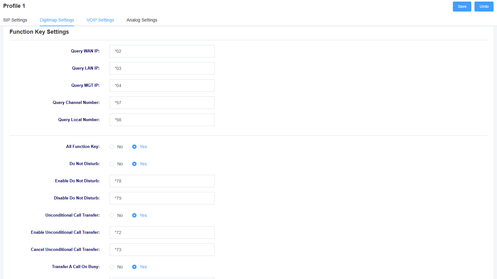
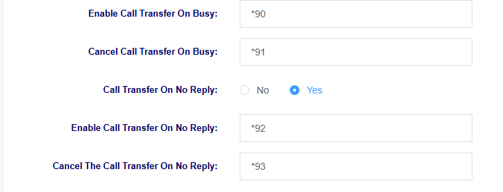
Table 4-2-1 Function Key Setting Parameter Descriptions
| options | instructions |
| Query WAN IP | Setting the function key for querying IP, the phone will play the device IP after dialing. |
| Query LAN IP | Setting the function key for querying IP, the phone will play the device IP after dialing. |
| Query MGT IP | Setting the function key for querying IP, the phone will play the device IP after dialing. |
| Query Channel Number | Setting the function key for querying the channel number, which will be broadcasted after the phone dials. |
| Search for local number | Setting the function key for inquiring the local number, the phone will play the local number after dialing. |
| All Function Keys | Select to enable or disable function keys |
| Do Not Disturb | Choose to enable or disable the Do Not Disturb feature |
| Enable Do Not Disturb | Set the function key to enable Do Not Disturb, and Do Not Disturb will be enabled at that extension after the phone dials it. |
| Disable Do Not Disturb | Setting the function key for cancellation of do-not-disturb, which will be cancelled at the extension after the phone is dialed |
| Unconditional Call Transfer | Select to enable or disable the Unconditional Call Transfer feature |
| Enable unconditional call forwarding | Set the feature key to enable Unconditional Call Transfer, the phone dials the feature key plus the extension number of the call forwarding, the Unconditional Call Transfer will be enabled at that extension |
| Set the function key to cancel Unconditional Call Transfer, the phone dialing will cancel Unconditional Call Transfer at that extension | |
| Transfer A Call On Busy | Select to enable or disable the Transfer A Call On Busy feature |
| Enable Call Transfer On Busy | Set the feature key to enable Transfer A Call On Busy, the phone dials the feature key plus the extension number of the call forwarding, the Transfer A Call On Busy will be enabled at that extension |
| Cancel Call Transfer On Busy | Setting the function key for cancelling Transfer A Call On Busy, the phone dialing will cancel busy call forwarding at that extension |
| Call Transfer On No Reply | Select to enable or disable Call Transfer On No Reply |
| Enable Call Transfer On No Reply | Set the feature key to enable Call Transfer On No Reply, the phone dials the feature key plus the extension number of the call forwarding,Call Transfer On No Reply will be enabled at that extension |
| Cancel The Call Transfer On No Reply | Set the function key for cancelling Call Transfer On No Reply, and the phone dialing will cancel nCall Transfer On No Reply at that extension |
4.3 VOIP Settings
On this interface, users can set VOIP related parameters.
Figure 4-3-1 VOIP Settings

Table 4-3-1 Description of VOIP Setting Parameters
| options | instructions |
| Allow call forwarding | Select whether to enable call forwarding |
| RTP alive sending interval | Setting the RTP alive sending interval |
| Call RTP timeout | Setting the call RTP timeout |
| Call Hold RTP Timeout | Setting the call hold RTP timeout |
| DTMF mode | Sets the DTMF mode, with options for RFC4733, inband, info, auto, and auto_info. |
Figure 4-3-2 VOIP Settings
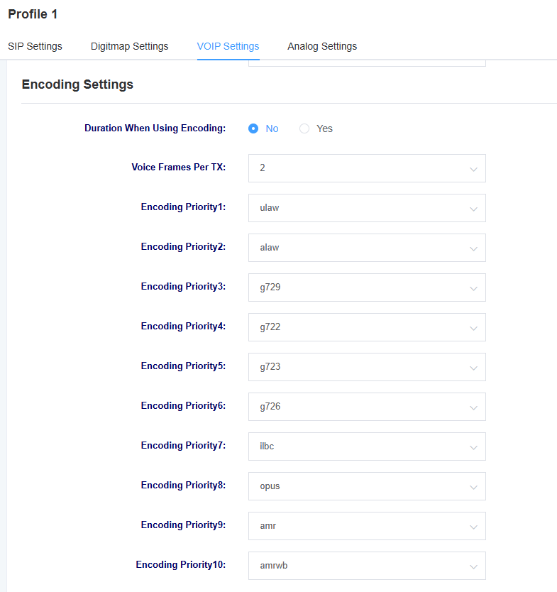

Table 4-3-1 Description of VOIP Setting Parameters
| options | instructions |
| Length of time to use coded packages | Choose whether to use encoded packet durations to make more efficient use of bandwidth and resources during transmission, storage and processing |
| coding priority | Setting the priority of the encoding |
| Enable UDPTL | Select whether to enable UDPTL |
| UDPTL error correction | Select UDPTL error correction |
4.4 Analog Settings
Figure 4-4-1 Analog Setting Screen
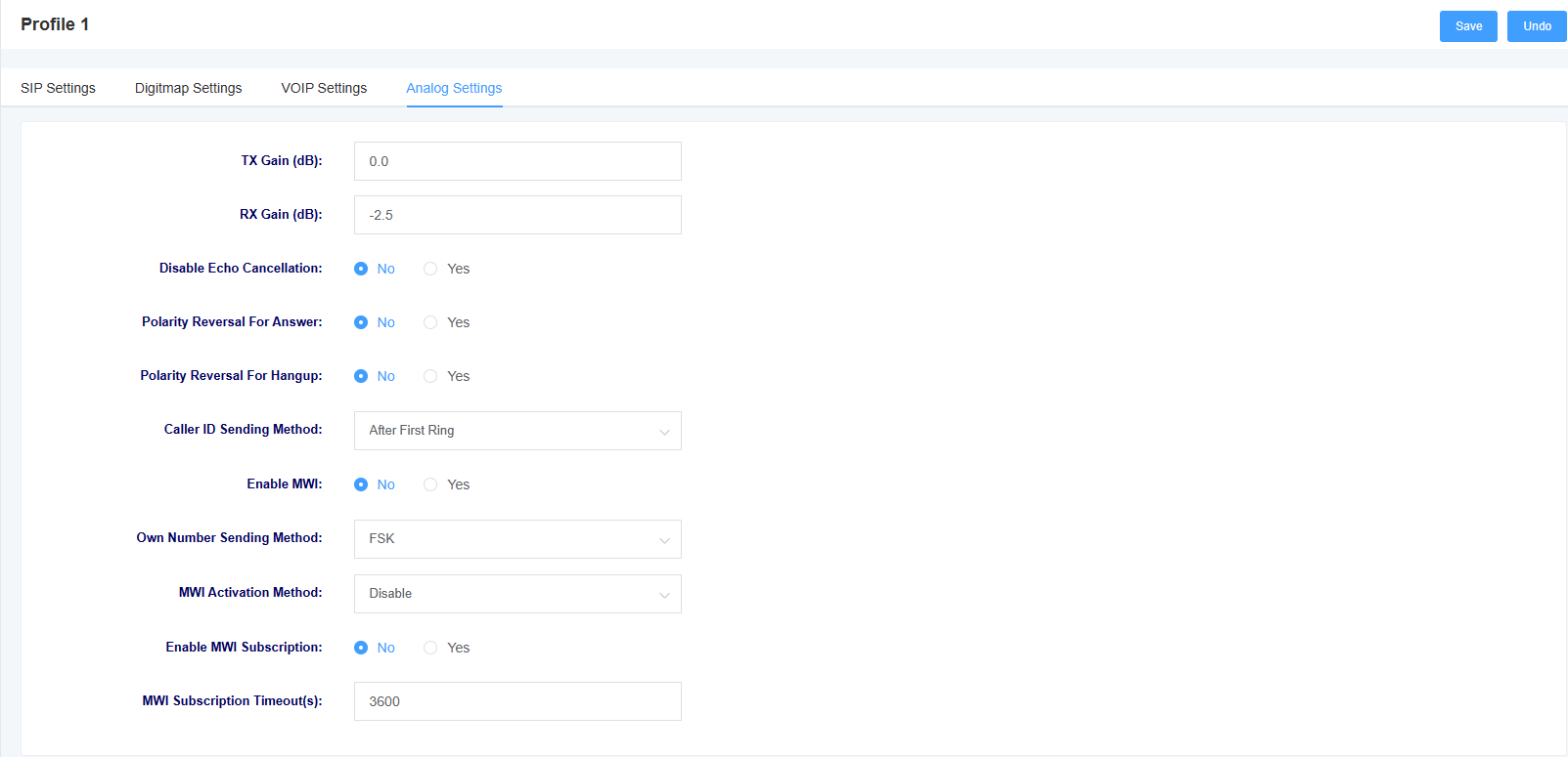
Table 4-4-1 Analog Setting Parameter Descriptions
| options | instructions |
| TX Gain | Setting the sound gain for transmitting |
| RX Gain | Setting the received sound gain |
| echo cancellation | Select whether to enable echo cancellation |
| Polarity reversal indicates an answer | Select whether to turn on polarity reversal to indicate an answer |
| Reversed polarity indicates a hang-up | Select whether to turn on polarity reversal to indicate a hang-up |
| Calling Number Delivery Method | Selecting the Calling Number Delivery Method |
| Enable MWI subscription and local number display | Set whether to enable MWI subscription and local number display, if enabled, the local number will be displayed on the screen of the handset when it is on-hook. |
| Local number display method | Selecting the local number display method |
| Message light mode | Choose how to illuminate the message light |
5. FXS port settings
In this screen, you can set the FXS port.
5.1 Basic Settings
Figure 5-1-1 Basic Settings

Table 5-1-1 Description of Basic Setting Parameters
| options | instructions |
| SIP User ID | Set the SIP user corresponding to this FXS port |
| Authentication ID | Set the authentication ID corresponding to this SIP user ID |
| Password | Setting the password corresponding to the authentication ID |
| Username | Setting the caller display name |
| Profiles | Select the template to use |
| Enabling ports | Select whether to enable the port |
| Enabling Registration | Select whether to enable registration |
| Group ID | Set Group ID |
5.2 Call Settings
Figure 5-2-1 Call Settings

Table 5-2-1 Description of Call Settings Parameters
| options | instructions |
| Hotline Number | Setting the hotline number of the port, if the number is not dialed within the hotline delay time after switch off, the hotline number will be dialed automatically |
| Hotline Delay(s) | Setting the hotline delay time |
| Call Waiting | Select whether to enable call waiting |
| Call Forwarding | Select whether to enable call forwarding |
| Call Hold | Select whether to enable call parking |
| Three-Way Call | Select whether to enable three-way calling |
| Do Not Disturb | Choose whether or not to turn on Do Not Disturb |
| Unconditional Transfer | Setting up an unconditional transfer number |
| Busy transfer | Setting the busy transfer number |
| Unresponsive Transfer | Setting the no-answer transfer number |
5.3 Advanced Settings
Figure 5-3-1 Advanced Settings

Table 5-3-1 Description of Call Setup Parameters
| options | instructions |
| FROM Forced Users | Setting the FROM force user |
| Using the P-Asserted-Identity header field | Carrying “P-Preferred-Identify” in INVITE, the P-Preferred-Identify header can be used to indicate the user’s identity in an anonymous call. |
| Using the Remote Party ID header field | Use the Remote Party ID header field to get the CID |
| Using the User=Phone header field | Carry “user=phone” in the URI to retrieve the called number from the user name when calling out to the PSTN network. |
| Using the P-Accesd-Network-Info header field | Use the P-Accesd-Network-Info header field to obtain the CID |
| Use of the P-Emergency-Info header field | Use the P-Emergency-Info header field to obtain a CID |
6. Advanced Configuration
6.1 Fax parameters
Under this page, you can configure fax-related parameters.
Figure 6-1-1 Fax Parameters

Table 6-1-1 Network Setting Description
| options | instructions |
| Modem Type | Setting supported modem types |
| maximum Rate | Select the maximum rate supported by fax |
| minimum Rate | Select the minimum rate supported by fax |
| error checking | Select whether to enable error checking |
| two-way negotiation | Select whether to enable two-way negotiation |
| Fax Tone Detection Duration | Setting the Fax Tone Detection Duration |
6.2 Qos Settings
You can set the TOS of RTP voice message and SIP signaling message under this interface.
Figure 6-2-1 Qos Setting Screen

6.3 Analog Settings
This screen allows you to set parameters related to the analogue line, such as echo cancellation and jitter buffer.
Figure 6-3-1 Analog Setting Screen
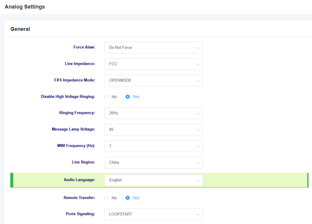
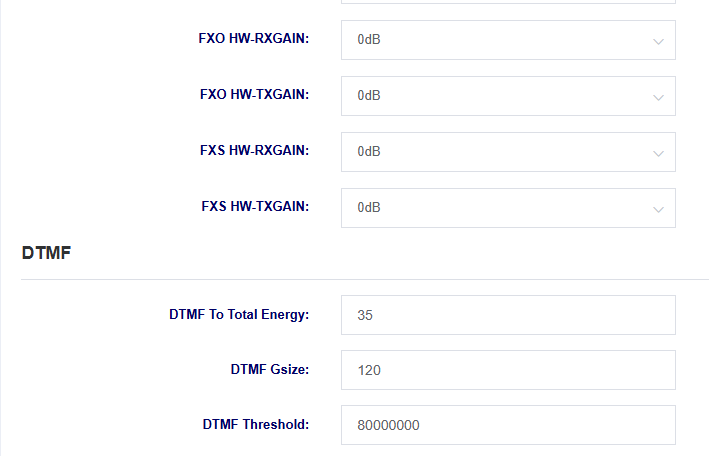
Table 6-3-1 Analog Setting Parameters
| options | instructions |
| Force Alaw | Select whether or not to enable this option, enabling it will force alaw |
| Line Impedance | Selection of line impedance |
| FXS impedance mode | Select FXS impedance mode |
| Disable High Voltage Ringing | Select whether to enable high voltage ringing |
| ringing frequency | Select ringing frequency |
| Message Lamp Voltage | Select message lamp voltage |
| MWI Frequency | Select MWI frequency |
| Line Region | Select the area where the line is located |
| Audio Language | Selecting the language for voice prompts |
| Remote Transfer | Whether to open Remote Transfer or not |
| Ports Signaling | Select ports signaling |
| FXO HW-RXGAIN | Setting FXO RXGAIN |
| FXO HW-TXGAIN | Setting FXO TXGAIN |
| FXS HW-RXGAIN | Setting FXS RXGAIN |
| FXS HW-TXGAIN | Setting FXS TXGAIN |
Figure 6-3-2 Analog Setting Screen
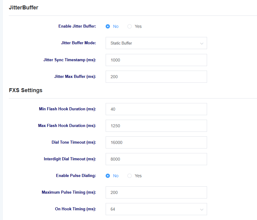
Table 6-3-2 Analog Setting Parameter Description
| options | instructions |
| Jitter buffer | Select whether to enable jitter buffering |
| Jitter buffer method | Select jitter buffer method |
| Jitter Synchronization Timestamp | Setting the jitter synchronization timestamp |
| Jitter Maximum Buffer | Setting the jitter maximum buffer |
| options | instructions |
| Minimum fork length | Setting the Minimum Tap Fork Duration |
| Maximum fork length | Setting the maximum duration of the tapping fork |
| Dial Tone Timeout | Setting the Dial Tone Timeout |
| Interdigit Dial Timeout | Setting the Interdigit Dial Timeout |
| Enable Pulse Dialing | Select whether to enable Pulse Dialing. |
| Maximum Pulse Timing | Setting the maximum pulse duration |
| On Hook Timing | Setting the maximum hang time |
Figure 6-3-3 Analog Setting Screen
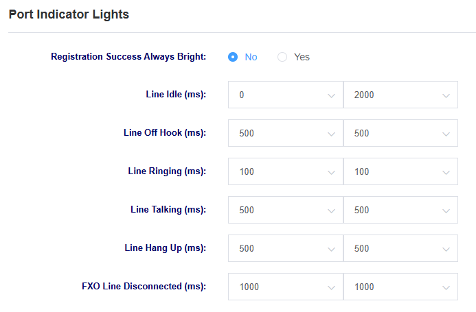
6.4 VOIP Settings
Under this page, you can make VoIP-related settings, such as call settings and session settings.
Figure 6-4-1 VoIP Settings
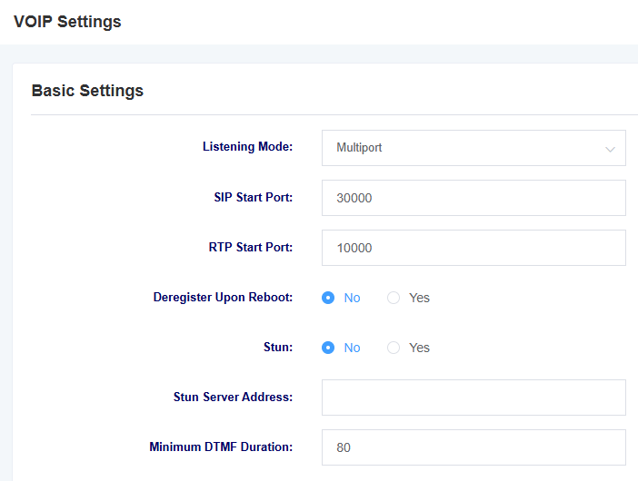
Table 6-4-1 Description of VoIP Setting Parameters
| options | instructions |
| listener mode | Select listening mode, multi-port and single port available |
| Sip Starting Port | Setting the starting port for SIP |
| Rtp start port | Setting the starting port for RTP |
| Deregistration on reboot | Select whether to deregister on reboot |
| Stun | Select whether to enable Stun |
| Stun Server Address | Setting the Stun server address |
| Minimum DTMF Duration | Setting minimum DTMF duration |
Figure 6-4-2 VoIP Settings
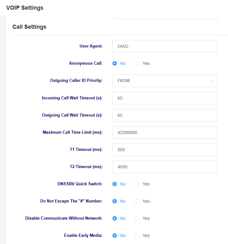
Table 6-4-2 Description of VoIP Setting Parameters
| options | instructions |
| User Agent | Setting the User Agent |
| anonymous caller ID | Select whether to allow anonymous inbound calls |
| Calling Number Display Priority | Select the calling number to be displayed preferentially from the FROM field or the P-Assertd-Identity field. |
| Inbound wait timeout | Setting the inbound wait timeout |
| Outgoing wait timeout | Setting the outbound wait timeout |
| Call Maximum Time Limit | Set the maximum time limit for a call, after which the call will be hung up |
| T1 timeout | Setting the T1 timeout |
| T2 timeout | Setting the T2 timeout |
| DNSSRV Quick Switch | Select whether or not to enable DNSSRV Quick Switch |
| Do Not Escape The “#” Number | Select whether or not to escape the “#” |
| Disable Communicate Without Network | Select whether or not to switch off the communicate without network |
| Early Media | Select whether to enable Early Media |
Figure 6-4-3 VoIP Settings
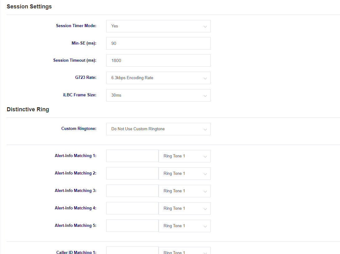
Table 6-4-3 Description of VoIP Setting Parameters
| options | instructions |
| Session Timer Mode | Select Session Timer Mode |
| Min-SE | Setting the minimum session timeout length |
| session timeout | Setting the session timeout |
| G723 Rate | Setting the encoding rate |
| iLBC Frame Size | Setting the iLBC frame size |
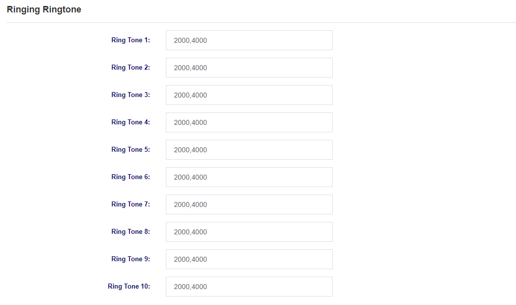
| Distinctive Ringing | Setting different ring tones |
Figure 6-4-4 VoIP Setting
6.5 Security settings
You can upload certificates under this page.
Figure 6-5-1 Security Settings Screen

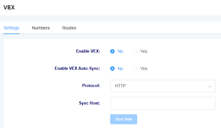
6.5 VEX
You can set VEX under this page. You can refer to How to use VEX
7 Maintenance
7.1 Automatic Restart
In this page, you can set the automatic reboot function, and the device can reboot according to the set time.
Figure 7-1-1 Auto Reboot Screen

7.2 Factory Reset
After clicking the Restore Factory button, the device will automatically reboot and restore the factory settings.
Figure 7-2-1 Factory Reset Interface

7.3 Auto Provision
iAG801 supports automatic deployment of configuration file and upgrade file functions, which can be set on this page.
Figure 7-3-1 Auto Provision Interface
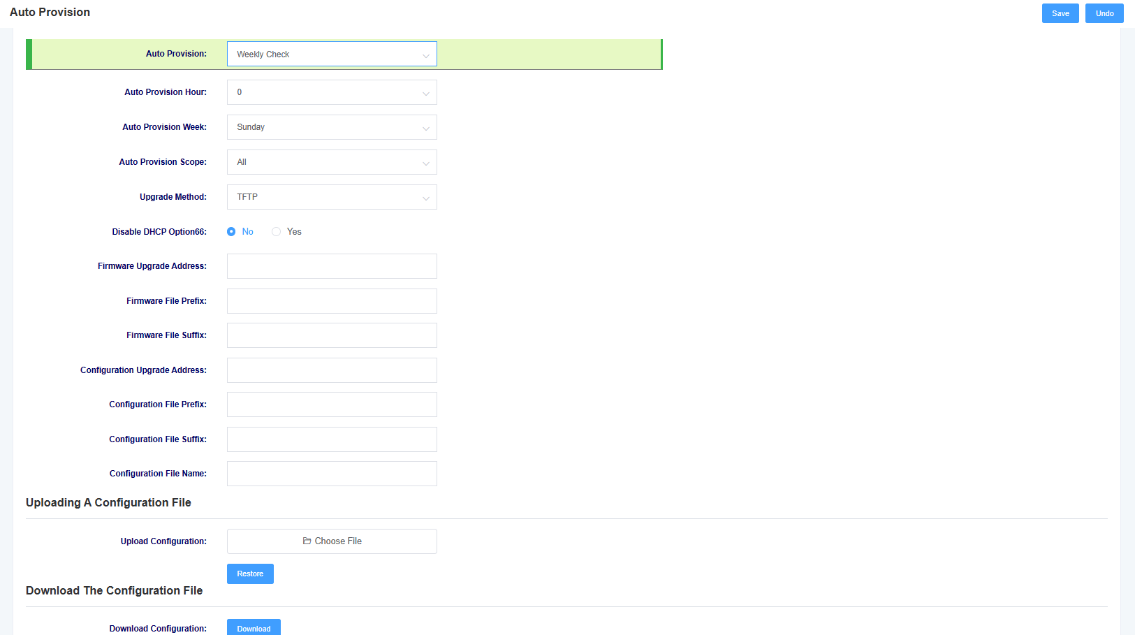
Table 7-3-1 Auto Provision Parameter Description
| options | instructions |
| automatic deployment | Set the mechanism of automatic deployment, you can choose to deploy automatically after each power-up or according to the set time cycle of deployment |
| Scope of automated deployment | Select the scope of automatic deployment, optional configuration files and upgrade firmware |
| Upgrade Method | Select the automatic deployment upgrade method, support tftp, http, https |
| Enable DHCP option66 | Select whether to enable DHCP option66 to get the file |
| options | instructions |
| Firmware upgrade address | Setting the path for firmware upgrade |
| Firmware file prefix | Setting the firmware file prefix |
| Firmware File Suffix | Setting the firmware file suffix |
| Configure the upgrade address | Setting the path for configuration upgrade |
| Configuration file prefix | Setting the configuration file prefix |
| Configuration file suffix | Setting the configuration file suffix |
| Upload Configuration | Uploading configuration files |
| Download Configuration | Download a file of the device’s current configuration |
The file name needs to be modified according to the rules, the master control firmware file name rules for (pre) (firmware model).img (post), interface board firmware file name rules for (pre) ixu (mac).img (post), configuration file name rules for (pre) cfg (mac) (post), pre is the prefix, post is the suffix, prefix suffix can be left blank.
7.4 Firmware Upgrades
You can upgrade the firmware on this page, select the corresponding firmware type and then upload the file to upgrade. You can choose whether to keep the system configuration or not, if not, the device will erase the system configuration after the upgrade.
Figure 7-4-1 Firmware Upgrade

7.5 Time Settings
This page allows you to set the time of the device. Users can set the time zone and set the NTP server address to automatically synchronise the time.
Figure 7-5-1 Time Setting

Table 7-5-1 Time Setting Parameter Description
| options | instructions |
| time zones | Setting the device’s time zone |
| system time | Display system time |
| Enable NTP time synchronization | Select whether to enable NTP time synchronization |
| NTP server address | Setting the NTP server address |
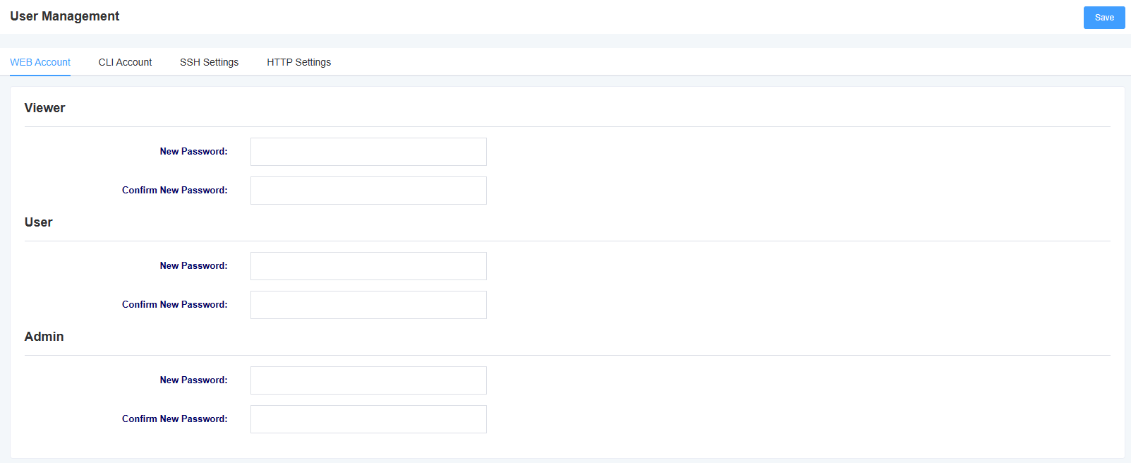
7.6 User Management
The iAG801 supports different user roles to login with different privileges. Under the user management page, you can change the password, switch the SSH function and make HTTP settings for different roles.
Figure 7-6-1 User Management


7.7 Network Capture
The iAG801 supports network packet capturing to locate network problems. Users can define the interface for capturing packets as well as select the protocol type, address and port from this interface.
Figure 7-7-1 Network Packet Capture

7.8 Log management
In the log management interface, you can set the address and port of the log server, as well as select the kernel log level to facilitate viewing device logs for technical analysis.
Figure 7-8-1 Log Management

Syslog, often referred to as syslog or system logging, is a standard for delivering logged messages over Internet Protocol (TCP/IP) networks. The term is often used to refer to the actual syslog protocol, or to applications or databases that send syslog messages. syslog is a master-slave protocol: a syslog sender transmits a small text message (less than 1024 bytes) to a syslog receiver. The receiver is usually named “syslogd”, “syslog daemon” or syslog server. Syslog messages can be transmitted using UDP and/or TCP protocols.
7.9 SNMP
In this page, you can set the information about SNMP service. iAG801 supports SNMPv1 and v2c.
Figure 7-9-1 SNMP

7.10 Cloud Management
In this page, you can set the information related to cloud management. iAG801 supports the cloud management function of Openvox, and after entering the server address port and binding code, you can manage the device on the cloud management platform.
Figure 7-10-1 Cloud Management Settings

Figure 7-10-2 Cloud Management Binding

7.11 UPnP
In this page, you can set UPnP port.
Figure 7-11-1 UPnP
7.12 Whitelist
In this page, you can set the information about the whitelist. After setting, only the IPs in the whitelist can access the device.
Figure 7-12-1 Whitelist Settings

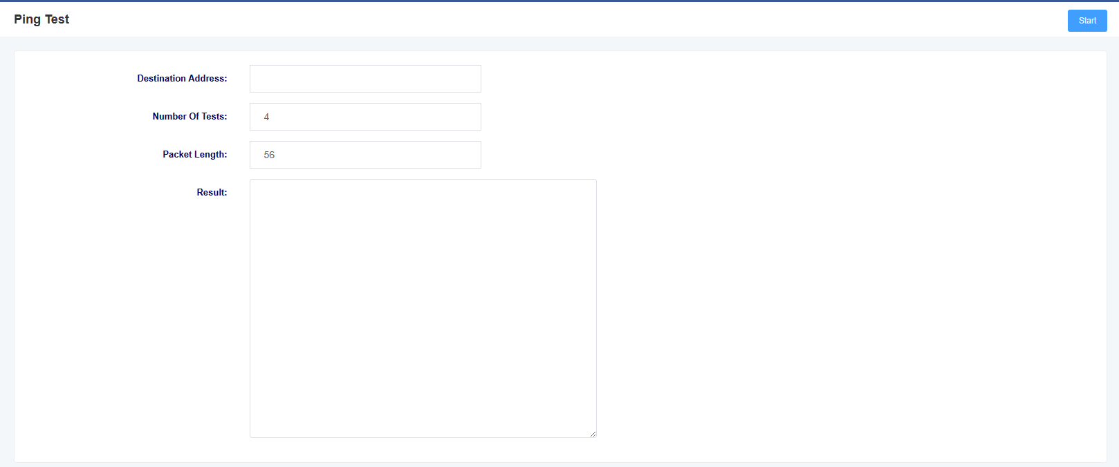
7.13 Ping Test
On this page you can use the ping command to test network connectivity.
Figure 7-13-1 ping test
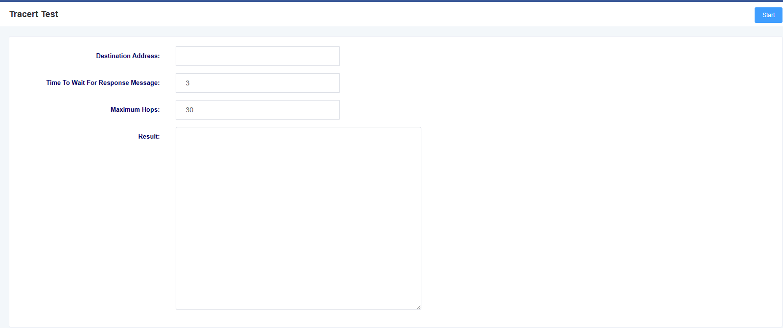
7.14 Tracert Test
On this page you can use the tracert command to test network connectivity.
Figure 7-14-1 Tracert Test
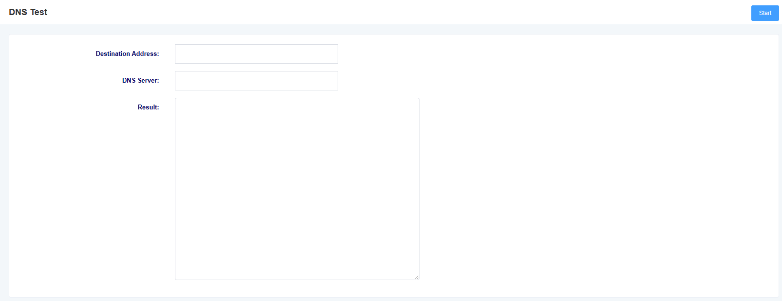
7.15 DNS Test
You can test the specified DNS in this page.
Figure 7-15-1 DNS Test
7.16 Port Recording
On this page you can select a specific port to record on to troubleshoot the problem.
Figure 7-16-1 Port Recording

7.17 Port test
On this page you can select a specific port to record on to troubleshoot the problem.
Figure 7-17-1 Port Test

Terminology
– DNS: Domain Name System
– SIP: Session Initiation Protocol
– TCP: Transmission Control Protocol
– UDP: User Datagram Protocol
– RTP: Real Time Protocol
– PPPOE: point-to-point protocol over
– VLAN: Virtual Local Area Network
– ARP: Address Resolution Protocol
– CID: Caller Identity
– DND: Do NOT Disturb!
– DTMF: Dual Tone Multi Frequency
– NTP: Network Time Protocol
– STUN: Simple UDP Traversal of UDP over NAT
– PSTN: Public Switched Telephone Network

