Uscale user manual
Uscale X1900 Unified Gateway Product Overview
1 Product positioning and highlights
1.1 product positioning
X1900 series unified gateway is the switching equipment of open source communication IP voice solution, which meets the communication needs of different sizes and types of enterprises and provides professional IP voice solutions.
1.2 Product Highlights
The unified gateway has rich business and interface capabilities, and is easy to deploy and maintain.
1.1 product positioning
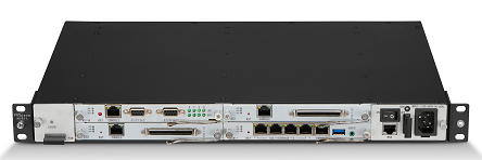
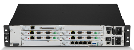
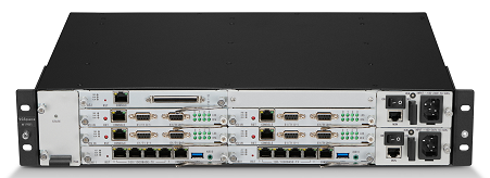
X1900 series unified gateway is the switching equipment of open source communication IP voice solution, which meets the communication needs of different sizes and types of enterprises and provides professional IP voice solutions. Table 1-1 lists the product models and applications of X1900 series unified gateways (hereinafter referred to as “unified gateways”).
Table 1-1 X1900 Series Product Models and Application Scenarios
| Product Model | Scope of application |
| X1911
|
Voice switching equipment for small and medium-sized enterprises can also be used as a local access gateway for small and medium-sized branches to meet the business needs of users below the 100.
1911 takes up less space (only 1U in height). |
| X1960
|
The voice switching equipment of medium-sized enterprises can also be used as the local access gateway of medium-sized branches to meet the business needs of 300~1000 users. |
| X1981
|
Large enterprise voice switching equipment can also be used as a local access gateway for large branches to meet the business needs of 1000 to 20000 users.
1981 takes up less space (height is only 2U). |
The product adopts pure SIP soft switch core, high integration, wide and narrow band integrated design, which can effectively improve communication efficiency and reduce operating costs.
The product realizes the analog phone and IP phone mixed network:
- Direct access to local analog phones.
- IP bearer network, through access gateway IAD (hereinafter referred to as IAD) access analog phone.
- IP bearer network, access to IP phone.
products through digital or analog trunk, as well as broadband SIP trunk and PSTN(Public Switched Telephone Network) or private network voice switching equipment.
1.2 Product Highlights
The unified gateway has rich business and interface capabilities, and is easy to deploy and maintain.
Rich business and interface capabilities:
- Built-in high quality voice conference resources and the Web conference management interface, use and management easy and convenient.
- Built-in voice mail, to achieve voice message function, to ensure that the call can be reached, not to miss important calls.
- Support one number, emergency call, secretary desk, call restrictions and other rich supplementary business, to meet a variety of use needs.
- Support PRA, QSIG, AT0, SIP multiple trunks, wide and narrow band integrated design, high integration.
High reliability, low cost
-
-
- Telecom level hardware and software platform, using CentOS operating system.
- X1960 and X1981 support 1+1 power backup
- 1981 X supports the main and standby of the main control board. The service interruption caused by the main board network cable failure can be recovered within 6s on the standby board, and the service interruption caused by other abnormalities of the main board can be recovered within 1s on the standby board. Voice calls in progress during the master/slave switchover are not affected.
- X1911, X1960 and X1981 support dual-machine master and standby. Voice calls in progress at the time of the master/slave switch are not affected.
- IP voice switching equipment can reduce enterprise operation and maintenance costs.
- Scalable and upgradeable to UC(Unified Communications) applications to protect existing investments
-
Flexible deployment and easy maintenance
-
-
- Supports multiple networking modes, such as single-node networking and distributed networking, for flexible deployment.
- Support unified network management to meet the needs of centralized operation and maintenance and efficient management.
- Web management system for quick start and daily configuration.
- Web self-service system, providing conference booking and personal business management functions.
-
2 Application Scenarios
The unified gateway is applicable to the following application scenarios.
2.1 single node networking
For those enterprises that 20000 less than user capacity and do not have branch offices, or branch offices do not have local regeneration needs, single-node networking can be used. The unified gateway and service servers are centrally deployed in the enterprise data center, and all end users are centrally registered to the unified gateway. In the case of a small branch office, you can deploy IAD proxy user registration to the unified gateway, or deploy IP phone registration to the unified gateway.
2.2 Distributed Call Management Networking (Peer-to-Peer)
For enterprises with 10000 to 30000 user capacity, peer-to-peer distributed call management networking can be adopted. The unified gateway is deployed in 2 or 3 nodes respectively, and the call service of this node is provided separately. The nodes are interconnected through SIP trunking to achieve call routing between different nodes.
2.3 distributed call management networking (convergence mode)
30000 more than the user capacity of the enterprise, you can use four or more unified gateway to form a convergence mode of distributed call management networking.
2.1 single node networking
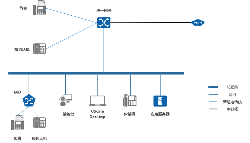
For those with less than 20000 user capacity and no branch office, single node networking can be used. The unified gateway and service servers are centrally deployed in the enterprise data center, and all end users are centrally registered to the unified gateway. In the case of a small branch office, you can deploy IAD proxy user registration to the unified gateway, or deploy IP phone registration to the unified gateway.
Networking Scheme
Figure 1 shows a typical networking solution for single-node networking.
Networking Description
- Analog phones and fax machines can access the unified gateway through analog telephone lines, and IP phones and SoftPhone terminals can access the unified gateway through IP networks.
- The unified gateway may interface with the PSTN through a trunk.
- The unified gateway provides voice mail and voice conferencing services for enterprise users.
Description:
X1911/X1960/X1981 all have built-in voicemail function.
- By default, the unified gateway acts as an IP PBX and can provide basic voice communication and supplementary services for enterprise users. The unified gateway can also be used as an access gateway to register to the IMS network through SIP trunking, so that enterprise users can use the services provided by the IMS network.
Description
Please deploy firewalls at the egress and ingress of the enterprise network and user access points, and formulate access control policies based on the communication matrix.
2.2 Distributed Call Management Networking (Peer-to-Peer)
For enterprises with 10000 to 30000 user capacity, peer-to-peer distributed call management networking can be adopted. The unified gateway is deployed in 2 or 3 nodes respectively, and the call service of this node is provided separately. The nodes are interconnected through SIP trunking to achieve call routing between different nodes.
Networking Scheme
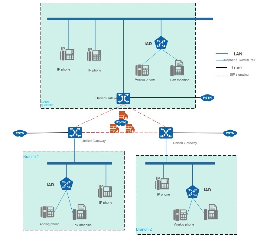
A typical networking scheme for peer-to-peer distributed call management is shown in Figure 1. The network is suitable for X1911/X1960/X1981.
Figure 1 Distributed call management networking (peer-to-peer)
Networking Description
- The unified gateway is deployed in each node and is responsible for user registration, intra-office calls, and local PSTN calls under the node. Unified gateways are interconnected through SIP trunks to achieve call routing between different nodes.
- IP phones, attendant SIP users, UC soft terminal SIP users, IAD proxy analog phones and fax machines under each node are all registered with the unified gateway of this node.
- The unified gateway of each node can be connected to PSTN through PRA, QSIG, AT0 and other trunks to realize local exit.
Business servers are deployed in the headquarters, centralized business.
2.3 distributed call management networking (convergence mode)
30000 more than the user capacity of the enterprise, you can use four or more unified gateway to form a convergence mode of distributed call management networking.
Networking Scheme
Figure 1 shows a typical networking solution for distributed call management in the aggregation mode. The network is suitable for X1911/X1960/X1981.
Figure 1 Distributed call management networking (convergence mode)

Networking Description
- The unified gateway is deployed in each node and is responsible for user registration, intra-office calls, and local PSTN calls under the node.
- IP phones, attendant SIP users, UC soft terminal SIP users, IAD proxy analog phones and fax machines under each node are all registered with the voice gateway of this node.
- The voice gateway of each node can be connected to the PSTN through PRA, QSIG, AT0 and other relays to achieve local exit.
- The aggregation gateway provides an inter-node call routing function. The convergence gateways and the convergence gateways and the voice gateways are interconnected through SIP trunking. U1981 can be used.
- The aggregation gateway can be deployed in multiple units to realize master/standby or load sharing.
Business servers are deployed in the headquarters, centralized business.
3 X1911/X1960/X1981 Product Structure
About this chapter
This paper mainly introduces the hardware structure of U1910/U1930, such as chassis, single board and fan box.
3.1X1911 Chassis
The X1911 chassis provides a centralized and interconnected space for internal components, while preventing component contamination and protecting components from external damage.
3.2X1960 Chassis
The X1960 chassis provides a centralized and interconnected space for internal components, while preventing component contamination and protecting components from external damage.
3.3X1981 Chassis
The X1981 chassis provides a centralized and interconnected space for internal components, while preventing component contamination and protecting components from external damage.
3.4 veneer
The X1911/X1960/X 1981 single board includes a main control board (SCU), a media relay resource board (MTU), an analog user interface board (ASI), and an analog user and analog relay interface board (OSU).
3.5 power supply
X1911/X1960/X1981 support AC power. For X1960/X- 1981, in the configuration of dual power supply module, support the current and backup.
3.6 fan box
The fan box provides heat dissipation guarantee for the system work.
The fan box is located on the left side of the equipment and is of vertical plug-in type. Four fans are installed inside the X1911, and 3 fans are installed inside the X1960 and X1981.
3.7 cable
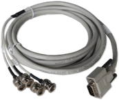
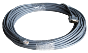
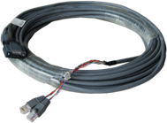
X1911/X1960/X1981 cables include digital trunk cables, high-density subscriber cables, and DC power cables.
3.1X1911 Chassis
X1911 1U(1U = 44.45mm) standard chassis, width 442mm, depth 310mm, high 44mm, can be installed in line with IEC(International Electrotechnical Commission) standard 19 inch cabinet, its appearance as shown in Figure 1.
Figure 1 Appearance of chassis

The slots are located on the front of the chassis. The X1911 provides one main board slot, three interface board slots, one power supply slot, and one fan box slot.
- Slot positions 0~2 are interface board slots for installing MTU board, ASI board or OSU board, supporting mixed insertion.
- Slot 3 is the main control board slot for installing SCU board.
Figure 2 Distribution of Chassis Slots

Description:
- The X -1911 interface board can be selected according to the system capacity. The empty slot of the interface board is not configured, and a dummy panel needs to be installed.
- In order to ensure the normal use of basic functions, X1911 needs to be equipped with at least one SCU board and one MTU board.
- If the device is installed on the cabinet with a hook screw, you do not need to use the M4 grounding screw; if the chassis is installed on the tray without the hook screw, you need to use the M4 grounding screw for grounding.
3.2X1960 Chassis
X1960 2U standard chassis, width 442mm, depth 310mm, high 86.1mm.
The chassis can be installed in IEC(International Electrotechnical Commission) standard 19 inch cabinet, its appearance as shown in Figure 1.
Figure 1 Appearance of chassis

The slots are located on the front of the chassis. The X1960 provides 1 main control board slot, 7 interface board slots, 2 power supply slots and 1 fan box slot.
- Slots 0 to 6 are interface board slots for installing MTU boards, ASI boards or OSU boards, supporting mixed insertion.
- Slot 7 is the main control board slot for installing SCU board.
Figure 2 Distribution of Chassis Slots

Description:
- The X -1960 interface board can be selected according to the system capacity. Empty slot for interface board or power supply not configured, dummy panel needs to be installed.
- In order to ensure the normal use of basic functions, X1960 needs to be equipped with at least one SCU board and one MTU board.
3.3X1981 Chassis
X1981 2U standard chassis, width 442mm, depth 310mm, high 86.1mm.
The chassis can be installed in IEC(International Electrotechnical Commission) standard 19 inch cabinet, its appearance as shown in Figure 1.
Figure 1 Appearance of chassis

The slots are located on the front of the chassis. The X1981 provides 2 main board slots, 6 interface board slots, 2 power supply slots and 1 fan box slot.
- Slots 0~2 and 4~6 are interface board slots for installing MTU board, ASI board or OSU board, supporting mixed insertion.
- Slots 3 and 7 are the main control board slots for installing SCU boards and supporting dual master control.
Figure 2 Distribution of Chassis Slots

Description:
- When only one main control board is installed in the slots of the two main control boards, the system runs in the single main control mode; when the slots of the two main control boards are fully configured, the system runs in the main and standby main control mode, which has higher reliability.
- The X -1981 interface board can be selected according to the system capacity. Empty slot for interface board or power supply not configured, dummy panel needs to be installed.
- In order to ensure the normal use of basic functions, X1981 needs to be equipped with at least one SCU board and one MTU board.
3.4 veneer
SCU/MTU/ASI/OSU Single Board Architecture
The X1911/X1960/X 1981 single board includes a main control board (SCU), a media relay resource board (MTU), an analog user interface board (ASI), and an analog user and analog relay interface board (OSU).
- SCU single board is X1911/X1960/X 1981’s main control board (required), and is the entire X1911/X1960/X1981 management control center, providing 4 network ports, 1 USB interface and 1 debugging serial port.
The main features of the board are as follows:
- Provide soft switching function.
- The media control protocol is processed.
- Support hot-plug operation.
Figure 1 shows the appearance of the SCU veneer panel.
Figure 1 Appearance of SCU Panel

| 1 | Indicator light |
| 2 | Reset button |
| 3 | Net port |
| 4 | Debug Serial Port |
| 5 | USB interface |
| 6 | Wrench |
Panel components are shown in the table below
| PANEL ASSEMBLY | Identification | Description · |
| Interface | 100/1000BASE-TX | The network port is used to connect the device to the LAN(Local Area Network) and is the external IP service interface of the device. Support RJ-45 socket, transmission distance is less than 100 meters.
Description: Network ports 1,2 and 3 can be connected to LAN, and network port 4 is an emergency repair port and is not used as a service interface. |
| CONSOLE | Debug serial port for device configuration and debugging. The interface adopts RS-232 standard serial port, supports RJ-45 socket, and the transmission distance is less than 10 meters. | |
| USB | Subsequent business extension interface (not used yet). | |
| AUDIO | 3.5mm external audio input interface (not used). | |
| Indicator light | ACT | The power indicator (green) reflects the input status of the power supply.
|
| RUN | The operation indicator (green) is used to reflect the operation status of the single board.
|
|
| ALM | Alarm indicator (red), used to reflect the alarm status of the board.
|
|
| Button | RST | The veneer reset button is used to restart the veneer.
Notice: Do not touch the reset button at will, otherwise it will cause the veneer to restart and cause the business being processed by the veneer to be interrupted. |
- The MTU board is a media trunk resource board and provides two physical E1/T1 interfaces (each interface can support two trunks). Each X1911/X1960/X1981 is equipped with at least one MTU single board.
MTU single board provides digital relay access, which is used to realize digital relay connection with higher-level bureaus, and provides number receiving, sound broadcasting, venue, TDM to VoIP function, and T.30 to T.38 fax function. Support hot-plug operation.
Figure 1 shows the panel appearance of the MTU single board.
Figure 1 Appearance of MTU panel
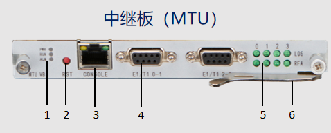
| 1 | Working indicator light |
| 2 | Reset button |
| 3 | Debug Serial Port |
| 4 | E1/T1 interface |
| 5 | Signal Indicator |
| 6 | Wrench |
The panel components are shown in the following table:
| PANEL ASSEMBLY | Identification | Description |
| Interface | E1/T1 | The digital relay interface is used to realize the digital relay connection with the higher-level office (such as LE). The interface supports DB9 connectors.
The MTU board provides two E1/T1 physical interfaces, and each interface can support two trunks. (1) When E1 is used, PRA, QSIG, R2 and SS7 signaling are supported, and it can be connected to a 75Ω digital relay cable, or it can be connected to a 120Ω digital relay cable through a 75Ω-120Ω junction box. (2) When T1 is used, PRA, QSIG, R2 and SS7 signaling are supported and can be connected to a 100Ω digital trunk cable. |
| CONSOLE | Debug Serial Port | |
| Indicator light | PWR | The power indicator (green) reflects the input status of the power supply.
(1) The light is on, indicating that the single board has power input. (2) The light is off, indicating that there is no power input or single board failure. |
| RUN | The operation indicator (green) is used to reflect the operation status of the single board.
1) The light flashes (0.5Hz), indicating that the system is operating normally. (2) The light flashes (1Hz), indicating that the veneer is starting. 3) The lamp is always on, indicating that the veneer is faulty. (4) The light is off, indicating that there is no power input or single board failure. |
|
| ALM | Alarm indicator (red), used to reflect the alarm status of the board.
1) The light is always on, indicating that there is an alarm. (2) If the light is off, it means there is no alarm. |
|
| LOS | Loss of signal indicator (green) to reflect loss of signal.
1) The light is on, indicating that the signal is lost. 2) When the light is off, the signal is normal. |
|
| RFA | Remote alarm indication (green), used to reflect whether the peer device is faulty.
1) The light is on, indicating that the terminal equipment is faulty. 2) When the light is off, the opposite device is working normally. |
|
| Button | RST | The veneer reset button is used to restart the veneer.
Notice: Do not touch the reset button at will, otherwise it will cause the veneer to restart and cause the business being processed by the veneer to be interrupted. |
- The ASI single board is an analog user interface board that provides 32 FXS(Foreign Exchange Subscriber) interfaces. ASI single board is used to provide access to POTS phones, and each single board can provide access to 32 analog phones. Support hot-plug operation.
The panel appearance of the ASI veneer is shown in Figure 1.
Figure 1 Appearance of ASI panel

| 1 | Indicator light |
| 2 | Reset button |
| 3 | Debug Serial Port |
| 4 | FXS Interface |
| 5 | Wrench |
Panel components are shown in the table below
| PANEL ASSEMBLY | Identification | Description |
| Interface | FXS 1-32 | FXS interface, used to connect analog phones, can connect 32. The interface supports DB68 connectors. |
| CONSOLE | Debug Serial Port | |
| Indicator light | PWR | The power indicator (green) reflects the input status of the power supply.
(1) The light is on, indicating that the single board has power input. (2) The light is off, indicating that there is no power input or single board failure. |
| RUN | The operation indicator (green) is used to reflect the operation status of the single board.
(1) The light flashes (0.5Hz), indicating that the single board is operating normally and is in an idle state. (2) The light flashes (1Hz), indicating that the veneer is starting. 3) The light is always on, indicating that the veneer is not properly installed or the veneer is faulty. 4) The light is off, indicating no power input or single board failure. |
|
| ALM | Alarm indicator (red), used to reflect the alarm status of the board.
(1) The light is always on, indicating that the communication is abnormal, or the veneer is not installed correctly or the veneer is faulty. (2) The light is off, indicating that the veneer is operating normally. |
|
| Button | RST | The veneer reset button is used to restart the veneer.
Notice: Do not touch the reset button at will, otherwise it will cause the veneer to restart and cause the business being processed by the veneer to be interrupted. |
- The OSU single board is an analog user and analog trunk interface board, providing 12 FXS(Foreign Exchange Subscriber) interfaces and 12 FXO(Foreign Exchange Office) interfaces.
The OSU board is used to provide access of analog terminals and analog trunks, and each board can provide access of 12 analog terminals and 12 analog trunks. Support hot-plug operation.
Figure 1 shows the appearance of the OSU veneer panel.
Figure 1 Appearance of the OSU panel

| 1 | Indicator light |
| 2 | Reset button |
| 3 | Debug Serial Port |
| 4 | FXS/FXO Interface |
| 5 | Wrench |
The panel components are shown in the following table:
| PANEL ASSEMBLY | Identification | Description |
| Interface | FXS 1-12 | FXS interface, used to connect analog terminals, can connect 12. The interface supports DB68 connectors. |
| FXO 1-12 | FXO interface, used to connect analog trunks, can connect 12. The interface supports DB68 connectors. | |
| CONSOLE | Debug Serial Port | |
| Indicator light | PWR | The power indicator (green) reflects the input status of the power supply.
1) The light is on, indicating that the single board has power input. 2) The light is off, indicating no power input or single board failure. |
| RUN | The operation indicator (green) is used to reflect the operation status of the single board.
(1) The light flashes (0.5Hz), indicating that the veneer is operating normally and is in an idle state. (2) The light flashes (1Hz), indicating that the veneer is starting. (3) The light is always on, indicating that the veneer is not installed correctly or the veneer is faulty. (4) The light is off, indicating that there is no power input or single board failure. |
|
| ALM | Alarm indicator (red), used to reflect the alarm status of the board.
1) The light is always on, indicating that the communication is abnormal, or the veneer is not properly installed or the veneer is faulty. (2) The light is off, indicating that the veneer is operating normally. |
|
| Button | RST | The veneer reset button is used to restart the veneer.
Notice: Do not touch the reset button at will, otherwise it will cause the veneer to restart and cause the business being processed by the veneer to be interrupted. |
3.5 Power Supply
X1911/X1960/X1981 support AC power. For X1960/X, 1981 and backup are supported when dual power supply modules are configured. The appearance of the AC power module is shown in Figure 1.
Figure 1 Appearance of AC power module
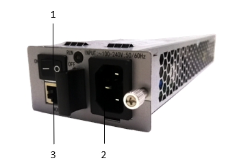
| 1 | Power switch |
| 2 | AC power interface |
| 3 | RJ45 interface |
The X1911 is configured with a single power supply module.
The X1960 and X are 1981 configurable with dual power modules. By default, a single power supply module is provided, which is located in slot 2 of the power supply. In the case of dual power supply modules, it has the following functions:
- Support current sharing and backup: during normal operation, multiple power modules can share the load with their own output current; when a power module stops working, other power modules play a backup role and assume their normal power supply tasks.
- Support hot plug: without turning off the power supply of the whole machine, the power supply module can be directly added at the empty slot of the power distribution frame; In the case of redundant backup of power supply, a power supply module can be directly pulled out without affecting the normal operation of the equipment.
3.6 fan box
The fan box provides heat dissipation guarantee for the system work.
The fan box is located on the left side of the equipment and is of vertical plug-in type. Four fans are installed inside the X1911, and 3 fans are installed inside the X1960 and X1981. The appearance of the fan box is shown in the following figure.
Figure 1 1911 Fan Box Appearance X
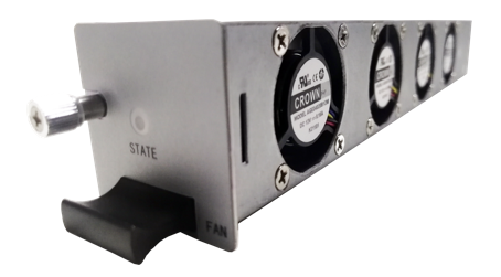
Fig. 2 1960 and 1981 fan box appearance X
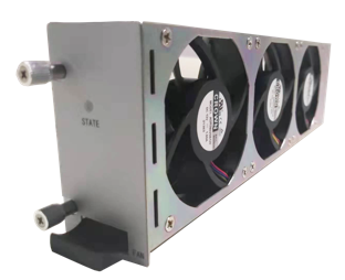
When the system is working, the fan blows the inside of the equipment, cold air comes in from the left side of the equipment, and hot air flows out from the right side of the equipment. The fan provides a powerful heat dissipation guarantee for the operation of the equipment and enhances the stability of the equipment.
3.7 cable
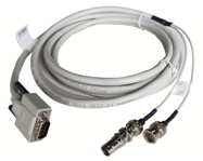
X1911/X1960/X1981 cables include digital trunk cables, high-density subscriber cables, and DC power cables.
Digital trunk cable, X1911/X1960/X1981 and various inter-office relay equipment connected to the cable, as shown in Table 1.
Table 1 Trunk Digital Cables
| Name | Picture |
| E1 Trunk | Figure 1 1E1 Trunk
Figure 2 2 E1 Trunk
|
| 75Ω-120Ω adapter box | 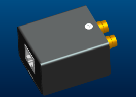
The adapter box can be used to convert 75 Ω unbalanced E1 signal into 120 Ω balanced E1 signal to meet E1 relay docking requirements. |
| T1 Trunk | Figure 3 1T1 Trunk
Figure 4 2T1 Trunk
|
The high-density subscriber cable is the cable connecting the analog phone to the FXS interface of X1911/X1960/X1981, as shown in Figure 5.
Figure 5. High-density subscriber cables
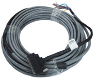
Power cord: To use an AC power supply, use an AC power cord, as shown in Figure 6.
Figure 6 Power Cord for AC
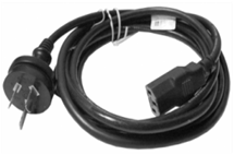
4 Features and functions
About this chapter
The unified gateway has rich features and functions, providing users with comprehensive and complete basic voice services and supplementary services.
4.1 basic voice service
4.2 supplementary business
4.3 Advanced Business
The unified gateway provides two advanced services: user rights hierarchical management and policy call restriction.
4.4 intelligent routing
Intelligent routing service refers to the IP failure after automatic reselection, and can according to the actual demand configuration relay routing strategy to achieve inter-office communication reliability and cost minimum requirements.
4.5 Voice Conference
According to the different ways of participants joining the meeting, voice conference can be divided into two types: reservation type and instant type, in which the reservation type meeting is divided into self-access type, chairman convening type and system convening type.
4.6 Voicemail Service
Voice mail service refers to the unified storage and management of voice messages. Users can extract the word crown to listen to the messages by dialing voice messages at any time and any place.
4.7 automatic switchboard business
Automatic switchboard service, also known as interactive voice response service, means that if a number is set as an automatic switchboard number, when calling the number, the voice prompt “please dial the extension number” will be played by default (custom switchboard can be configured) to realize the functions of playing and receiving the number and automatic transfer.
4.8 attendant desk
The unified gateway has a built-in hard phone console (hereinafter referred to as “hard phone console”), which can realize simple phone console service in cooperation with IP phone or POTS phone.
4.9 bill
The unified gateway generates user ticket information, writes and saves it to the ticket pool. When the unified gateway interfaces with the bill server, other applications can obtain and parse the bill through the bill server.
4.10 security
The unified gateway provides security for users.
4.1 Basic Voice Service
Voice Communication
The unified gateway supports basic voice communication, including intra-office user interworking, interworking based on narrowband relay and interworking based on broadband relay.
- Intra-office user interworking
Users in the unified gateway office can make voice calls to each other as calling or called. The user terminal may be various broadband and narrowband terminals supported by the device, including an analog telephone set, a SoftPhone, an IP telephone set (SIP), a SIP-based Desktop Client, a SIP attendant, and the like, and supports an access device such as an IAD(SIP).
- Interworking based on narrowband relay
The unified gateway can interwork with the traditional telephone network PSTN through digital trunking (E1/T1) or analog trunking (ATO). The in-office user may conduct a voice call with the user of the narrowband relay peer as a calling or called party.
- Table 1 lists the E1/T1 trunk types supported by the unified gateway.
| Relay Type | E1 | T1 |
| PRA | √ | √ |
| QSIG | √ | √ |
Description:
One E1 relay can provide up to 30 voice channels, and one T1 relay can provide up to 23 voice channels.
(1) Interworking based on broadband relay: The unified gateway can communicate with other IP PBX or softswitch systems through SIP relay, and can also access the IMS network through SIP relay. The user in the office can make a voice call with the user in the IP PBX, soft switching system or IMS network as the calling or called party.
Call permission control: The unified gateway supports four basic call permissions: intra-office call, local call, domestic long-distance call and international long-distance call permissions. On this basis, it also supports custom permissions and realizes some special call permission control.
Number analysis and processing: The unified gateway analyzes the calling and called numbers through the word crown and length of the number, and realizes the control of outgoing and incoming call permissions, thus completing the connection or restriction of the call. The analysis of the calling number is performed before the analysis of the called number. For the number of the same word crown, the analysis route can be realized by the number length.
The number analysis and processing capabilities of the unified gateway:(1) The maximum number length that supports analysis and processing is 32 bits, and the maximum length of the word crown is 32 bits. The maximum number of subscribers is 16 digits. (2) Support 1024 calling number analysis and 2048 called number analysis. (3) Support word crown call attribute analysis. The word crown attributes include emergency calls, local, local, local, domestic and international long-distance calls, and 32-level custom permissions. (4) Support insert/modify/delete operations according to the length of the calling and called numbers. The converted number length cannot exceed the maximum length. A total of 1024 number transformation types are supported.
Voice processing and coding: The voice processing capabilities of the unified gateway are as follows:
- Support echo cancellation, JitterBuffer and other functions, does not support other narrowband network optimization functions.
- TOS and DSCP are supported.
- Support for RTCP.
- G.711(A-Law / U-Law), G.729a/B, iLBC, G.722, G.722.1, G.722.2 and Opus codec formats are supported. At the same time, the system supports voice codec switching and priority selection to better meet customer needs.
Fax: The unified gateway supports circuit domain T.30 format fax, packet domain T.38 format fax, and G.711 transparent transmission.
- T.38 format fax, fax signal end-to-end delay can not exceed 3 seconds, and it is recommended that the actual network should not exceed 4 T.38 transcoding gateways.
- If it is G.729 voice coding mode of voice calls, support through re-negotiation to G.711 to complete transparent fax.
4.2 Supplementary Business
The following figure shows the supplementary services provided by the unified gateway.
| Business Name | Introduction |
| Voice call | Voice calls are made between telephone users in the PBX office or with telephone users outside the office. |
| Video Call | Two video phones make point-to-point video calls, and both parties can see each other’s videos. |
| Local number query | The user dials a number that has been configured to query the machine. |
| Calling Line Identification Display | The calling line identification display is the calling number display, and the caller number can be displayed on the user phone. |
| Calling Line Identification Limits | When the user acts as the caller, the number of the user (I. e., the calling number) cannot be displayed on the phone of the called user. |
| Built-in CRBT service | Play personalized ring tones to the calling party. |
| Call Hold | Users can temporarily interrupt an ongoing call and then resume the call when needed. |
| Call park | The user can put the current call on hold and then resume the held call on another phone in the office. If the user does not resume the call within the set time, the system will release the call and the held party will listen to the busy tone. |
| multi-way call | The user can handle multiple calls at the same time on a single phone, including incoming and outgoing calls, but can only make one voice call at the same time, and other calls are in a holding state. |
| Call Waiting | When a user is on a call, if a third-party user calls the user, the user will receive a call waiting prompt tone, indicating that another user is waiting for a call with the user. |
| Call Transfer | The user exits the call by himself or herself by pressing the transfer key to transfer the call to the third party during the call. |
| Call Deflection | When the user comes in, press the transfer key to transfer the call directly to the third party, but he does not answer. |
| Call Forward | Depending on the status of the user, the call to the user will be forwarded in different ways. |
| Hotline | The terminal automatically calls the preset number after off-hook. |
| On behalf of the answer | A user uses one phone to answer a ringing call on another phone. Designated Pickup means that the user uses one phone to answer a call that the designated phone is ringing. The same group answering means that users can use a 1 phone to answer incoming calls from a ringing phone in the same group. |
| Automatic callback | After the user dials a busy or unanswered internal phone, the system automatically calls the calling phone and the called phone when the dialed user is available after registering the call back. |
| abbreviated dialing | The user uses a self-numbered number instead of a longer telephone number. Self-numbered numbers are also called abbreviated numbers. Using abbreviated numbers can reduce dialing time and facilitate memory. |
| Do Not Disturb | In order to avoid the interruption of incoming calls, the user can temporarily stop the system from calling his own phone or soft terminal. |
| strong insertion | The operator can force the call to join the call of the telephone user in the office and make a three-way call. |
| Demolition | An operator can forcibly dismantle an in-office telephone user’s ongoing call. |
| One Pass | A user number is bound to multiple terminals, and a user can answer an incoming call on any ringing binding terminal. |
| Three-way call | On the basis of not interrupting the current call, the user can call the third-party user to implement the three-party common call. |
| Alarm clock business | The phone rings automatically at a time set by the user to alert the user. |
| Keep the music | The system plays enterprise-customized waiting music to call-on-hold users and is used in services such as call-on-hold, call transfer, and call residency. |
| Absent business | After the user registers the absent service, other users will hear an absent prompt tone when calling the user. |
| Paging Broadcast | One-way broadcasts to all members of the group using the telephone system. |
| Senior Manager Secretary | A senior manager secretary is a line that binds a line of a manager’s phone to a line of his secretary’s phone. The secretary and the manager can receive the call to the manager at the same time, and the manager can answer the call directly, or the secretary can answer the call first, manually screen the call and then transfer it to the manager for processing. |
| Emergency call | IP phone lock, unregistered and a variety of limited call cases, you can directly dial a specific number to achieve emergency call out. |
| Revoke all business | Cancels all supplementary services registered by a user, but the user’s business permissions are not affected. |
| Voice service password modification | The voice service password is used for outbound call restriction service, password call restriction service, number one service, cancellation of all services and voice mail service. Please modify regularly to improve the security of voice service. |
| Busy Light Area (BLF) | The call status (idle/in call/ringing/offline) of other users in the office can be subscribed to through the programmable keys of the IP phone. Before calling the user, the call state can be known first, and calling again in the idle state can improve the call success rate. |
| Call Authority Control | When the user initiates a voice call, the system determines whether to allow the call to be initiated according to the calling authority of the calling number and the call type of the called word crown. Call permissions can be flexibly controlled according to usage needs. |
| Black and white list call limit | The system decides whether to allow or reject a call based on the specific call restriction relationship of the black and white list. |
| Anonymous limited call | If the system cannot obtain the calling subscriber number, this call will be prohibited and the called subscriber’s telephone will not ring. |
| Exhalation Restrictions | Users can according to need, through a certain dial-up program, limit the phone’s call-out authority. |
| line-finding group | The enterprise can form a tracking group of users with the same work nature or the same department, and configure an access code for the tracking group. When the user dials this access code, the system assigns the call to the members of the group according to the pre-configured policy. When one of the members answers, the system will stop ringing. |
| co-vibration | A user binds a plurality of numbers to a main number, and when an incoming call is made to the main number, terminals of the main number and other bound numbers will ring at the same time, and after any terminal answers, the other terminals will stop ringing. |
| Shun vibration | A user binds multiple numbers to a main number, and when an incoming call is made to the main number, terminals of the main number and other bound numbers will ring in turn, and after any terminal answers, other terminals will stop ringing. |
| DID | External users can dial in-office users directly without going through the automatic switchboard extension. |
| automatic switchboard | Automatic switchboard is also known as interactive voice response service. Through automatic voice answering, the function of transferring the user’s incoming call to the extension is realized. |
4.3 Advanced Business
The unified gateway provides two advanced services: user rights hierarchical management and policy call restriction.
Hierarchical management of user rights: Users of the unified gateway can be divided into different rights levels, and users with different rights levels have different supplementary service rights and call rights. User permission levels are divided into four levels, from low to high: default, normal, advanced, and privileged. By default, users belong to the default permission level.
Classification of supplementary business permissions: Different levels have different supplementary business permissions. The supplementary business permissions owned by the lower permission level are a subset of the supplementary business permissions owned by the higher permission level. The business permissions corresponding to each level are shown in Table 1.
Table 1 Correspondence between user level and business authority
| User Level | Business Permission |
| Default Permissions | It has the local number inquiry, call forwarding, call forwarding, call waiting, abbreviated dialing, outgoing call restriction, alarm clock service, calling number display, password modification, telephone conference, call residence, phone call permission, one-number communication service, do not disturb, multi-call, immediate meeting and absent user service permission. |
| Normal Permissions | In addition to the default permissions, it also has the Busy Call (POTS users only), Busy Call Back, Assign Pickup, and Same Group Pickup business permissions. |
| Advanced Permissions | In addition to ordinary rights, it also has three-party call, ringing service (same vibration, shun vibration service), forced plug-in, forced demolition, hotline service, unconditional mailbox transfer, busy mailbox transfer, unanswered mailbox transfer, unconditional fax transfer, status forward transfer, conditional forward transfer, unanswered call back, BLF and offline mailbox transfer. |
| Special Permissions | In addition to having advanced permissions, there are privileged user business, secretary business, secretary desk business permissions. |
The outgoing call permission is graded and controlled by time: different user permission levels correspond to different call permissions, and can be associated with working hours, so that users at a certain level can only have a certain call permission within a certain period of time. The call authority setting of each level user is shown in Table 2.
Table 2 Correspondence between user level and outgoing permission
| User Level | Inboard Call (Inter) | Local Call (Local) | Domestic Long Distance (Ddd) | International (Idd) |
| Default Permissions | Yes | Yes | No | No |
| Normal Permissions | Yes | Yes | Restricted in working hours | No |
| Advanced User | Yes | Yes | Yes | Restricted in working hours |
| Special Permissions | Yes | Yes | Yes | Yes |
Policy call restriction: The unified gateway supports policy call restriction. The specific description of each policy call restriction is shown in Table 3.
Table 3 Policy call restriction description
| Policy Call Limit Name | Description |
| Limit calling with calling word crown | Analyze and restrict the calling word crown. |
| System-level black and white list mode call limit | The decision to allow or reject a call is based on the specific call restriction relationship of the black and white list. The blacklist and blacklist call limits are as follows:
(1) When the calling party is blacklisted, it can only call the called party of the white list. (2) When the calling party is a common call-limiting group, it can call the called party of the white list and the common call-limiting group, but cannot call the called party of the blacklist. (3) When the caller is a white list, it can call any callee. |
| Personal blacklist mode limited call | The decision to allow or reject a call is based on the specific call restriction relationship of the black and white list. The priority of personal blacklist is lower than that of system-level blacklist business. |
| Calling Number Authentication | This office user or the called word of the relay incoming call crown if configured with the service, then to the Radius server to initiate a calling number authentication request, authentication passed before the basic call connection; otherwise the call failed. |
| Anonymous limited call | If the user has this service right, all anonymous callers (including foreign office callers) to the user will be restricted. |
| Outbound call time limit | When the user makes domestic and international long-distance calls, the duration of the call can be limited according to the configuration, and the user is prompted one minute before the call duration is reached. |
Emergency call: to ensure that the IP phone and the unified gateway between the network can be reached, the user can in any state (not registered, call authority is insufficient, arrears, etc.) can be to the emergency call center to initiate a call, the latter according to the calling number can locate the call originator’s geographical location.
Note:(1) Emergency calls are not subject to call restrictions in the following scenarios: calling in arrears, password, card number, domestic long-distance, international long-distance, in-office and out-of-office. (2) Support emergency call function
4.4 Intelligent Routing
Intelligent routing service refers to the IP or TDM relay failure after automatic reselection, and can be configured according to the actual needs of the relay routing strategy to achieve inter-office communication reliability and cost minimum requirements.
(1) Route selection based on time period setting
Different time indexes are set for different bureau direction, and each time index corresponds to a specific time period (accurate to the hour). When the call is out, the time index is searched according to the current time and the corresponding bureau direction is selected. And IP PBX supports the way that multiple office-to-item selection codes share one office direction. That is, when configuring a bureau to, you can add a bureau to multiple bureau to the selection code, then the bureau to enjoy multiple different routing strategies at the same time. IP PBX will automatically select the corresponding routing strategy according to the outgoing word crown dialed by the user.
(2) Route selection based on rate setting
Different office directions set different rate reference values. When the call is out, the office direction with low rate reference value is preferred. When the office direction relay circuit is all busy, the office direction with low rate reference value is selected, and so on.
(3) Rerouting failed
When the routing fails according to the policy of the local bureau to the selection code, the backup bureau corresponding to the routing failure processing index is reselected according to the policy of the selection code. ,
(4) Route selection based on load sharing settings
Traffic is balanced according to preset multiple routes. The system polls the bureau direction in descending order of the bureau direction number until it finds a bureau direction with an idle circuit. Subsequent calls will be routed starting in the next office direction from the office direction selected by the previous call.
(5) Route selection by percentage setting
Different percentages are set for different direction, and when a call is out, it is selected between different direction according to the preset percentage. In addition to the allocation percentage of 100 per cent of the bureau to the outside, according to the allocation percentage of the bureau from large to small proportion to the rotation of the bureau.
(6) Route selection based on user level setting
Different user levels set different office direction, high-level users call out when the priority to use the user’s level of the office direction, when the failure of the route selection, and then to the lower level of the user level of the office to select the route.
After the configuration is based on the user’s level, the system will preferentially select the bureau direction of the user’s level to make an outgoing call. If there is no idle circuit in the bureau direction of this level, the bureau direction corresponding to the lower level user is selected, and so on. For bureau direction with the same grade, polling is carried out from small to large according to the bureau direction number. After setting the office with good performance to belong to high-level users, users with high permission level can enjoy better call quality, while users with low permission level cannot use these office direction.
(7) Route selection based on relay link equalization settings
The relay with the largest number of idle circuits is preferentially selected to achieve balanced allocation and use of each relay link.
4.5 Voice Conference
According to the different ways of participants joining the meeting, voice conference can be divided into two types: reservation type and instant type, in which the reservation type meeting is divided into self-access type, chairman convening type and system convening type.
(1) The meeting
Users can book meetings through the web self-service system built into the unified gateway. According to the different access methods, the reservation meeting can be divided into the following three types:
- Self-access type
Attendees join the meeting by dialing the pre-set meeting access code and then entering the meeting ID and meeting password according to the voice prompts.
- Chairman’s Convening
After the meeting chairman accesses the meeting through voice navigation, he calls the participants to join through the phone or Web self-service system.
- System call-up type
The list of participants and the meeting time are configured in advance, and the system automatically calls all participants to join the meeting at the preset time.
(2) The immediate meeting
The instant conference refers to that the conference chairman user does not need to book a conference in advance, but directly dials a conference access code on a terminal device, and then summons participants to attend the conference according to voice navigation.
4.6 Voicemail Service
Voice mail service refers to the unified storage and management of voice messages. Users can extract the word crown to listen to the messages by dialing voice messages at any time and any place.
Voice mail service, also known as VMS(Voice Mailbox Services), has voice messages, phone message lights, extract voice messages, delete voice messages, play voice messages and other functions.
According to the different ways of voice mail, voice mail service is divided into 4 types: unconditional voice mail, voice mail before no answer, voice mail before busy and voice mail before offline.
(1)X1911 maximum support 12 concurrent messages; X1960 and X1981 maximum support 30 concurrent messages. (2) It can provide up to 50 voice messages for each voice mailbox user with a maximum of 300s each.
4.7 Automatic Switchboard Business
Automatic switchboard service, also known as interactive voice response service, means that if a number is set as an automatic switchboard number, when calling the number, the voice prompt “please dial the extension number” will be played by default (which can be modified) to realize the functions of playing and receiving the number and automatic transfer.
Unified gateway built-in automatic switchboard service, specific specifications are as follows:
(1) The unified gateway supports the configuration of up to 256 automatic switchboard, of which the maximum number of customizable scripts is 245(2)X1981/X1960/X1911 supports the recording of announcement voice.
(3) The recording of up to 246 announcement voices is supported (I .e. the default automatic switchboard +245 custom automatic switchboard, each automatic switchboard can record 1 announcement voice, the maximum duration of each announcement voice is 300 seconds, and the total capacity of announcement voice is 64MB).
(4) Support switchboard and extension dialing (except AT0 incoming switchboard).
(5) Support to customize the voice prompt tone of the switchboard according to the time period, I .e. play different voice prompt tones of the switchboard in different time periods; Support the calling party to return to the switchboard to answer after the called extension hangs up first.
4.8 Attendant Desk
The unified gateway has a built-in hard phone console (hereinafter referred to as “hard phone console”), which can realize simple phone console service in cooperation with IP phone or POTS phone. You can also prepare the attendant console system to interface with the unified gateway to achieve more functions. The unified gateway hard attendant network is shown in Figure 1.
Figure 1 Networking of hard attendant console

When external users or enterprise users dial the access code of the attendant console, they can wait in line, and the system will automatically allocate idle operators (agents) to answer in turn. The operator can transfer the call to another operator. Authorized operators can also use forced insertion and forced demolition services.
4.9 Bill
The unified gateway generates user ticket information, writes and saves it to the ticket pool. When the unified gateway interfaces with the bill server, other applications can obtain and parse the bill through the bill server.
Tale Server
The ticket server (which needs to be installed separately) is used to store and process ticket data from multiple IP PBX hosts at the same time.
Description:
BMU or a third-party system is required to perform operations such as query and statistics in the dialog form.
Integrated ticket console function
The bill server provides a visual human-computer interaction interface for maintenance and management.
- Query bill
The user can query the single file on the single server by any combination of the calling number, the called number, the IP address of the device to which the single belongs, the time when the single is generated, and so on.
- Delete History Tale
Users can delete the single file stored on the single server to free up hard disk space. For the sake of data security, the system only allows the deletion of one month ago.
- View ticket pool information
Users can enter the corresponding IP PBX host IP address, view the host single pool status.
- bill transmission control
The user can set the transmission status of the bill. When a new bill is generated in the IP PBX bill pool, the bill server controls whether to automatically extract it from the bill pool according to the status. The ticket transmission state is enabled by default.
4.10 Security
The unified gateway provides security for users.
Protocol Attack Prevention
(1) Support to isolate management traffic and business traffic to different network segments through network port shunting, and bind management traffic to specific network ports to enhance system security.
(2) When the user logs in to the host device, the user provides SSH(Secure Shell) secure encryption protocol to log in.
(3) Support the use of SRTP media stream encryption and TLS(Transport Layer Security) signaling encryption in voice services to ensure the security of voice data.
Password Security
(1) When the user logs in to the Web interface for the first time, the user is prompted to change the password.
(2) The Web interface and command line authentication module adopt an anti-brute force mechanism to temporarily lock the account and IP address (Web only) after 3 consecutive failed login attempts.
(3) When logging in to the Web interface, the HTTPS security protocol is used to pass the user name and password to the server.
Web Security
(1) For each page or Servlet request that requires authorization to access, it verifies whether the user’s session ID is valid and whether the user is authorized to perform this operation. The final authentication process of (2) is performed on the server. (3) The data generated by the user is verified on the server side; the data will be HTML encoded before being output to the client to prevent the execution of malicious code and cross-site scripting attacks. (4)Web servers and Web applications are scanned by Web security scanning software, and there are no high-level vulnerabilities.
5.Operation,maintenance and management
Through the Web management system and the realization of the unified gateway management, through the Web self-service system to complete the conference management, business registration and other operations, in order to achieve the unified gateway operation and maintenance.
5.1Web Management System
The Web management system is a built-in configuration and monitoring tool of the unified gateway, which can be accessed through a browser and provides configuration management and resource query functions.
5.2Web self-service system
The unified gateway provides a Web self-service system, and ordinary users can access it through a browser to easily complete conference management, business registration, business password maintenance and other operations.
5.1 Web Management System
The Web management system is a built-in configuration and monitoring tool of the unified gateway, which can be accessed through a browser and provides configuration management and resource query functions.
The functions provided by the Web management system are shown in Table 1.
Table 1 Main functions of Web management system
| Management function | Function children |
| Configuration Management | Provide configuration wizard for single board configuration, user configuration, relay configuration
Provide visual interface for data configuration, business configuration and networking configuration |
| Resource Monitoring | Single board status monitoring
CPU Status Monitoring |
5.2 Web self-service system
The unified gateway provides a Web self-service system, which can be accessed by ordinary users through a browser to easily complete operations such as conference management, business registration, and business password maintenance. The functions provided by the Web self-service system are shown in Table 1.
Table 1 Functions provided by the Web self-service system
| Business function | Description |
| Scheduled Meetings | Schedule meetings and increase the number of participants as required |
| View Meeting | View related meetings and be able to join directly |
| Call an immediate meeting | Convene immediate meetings and increase the number of participants as required |
| Business Registration | Registration and cancellation of number one service, call forwarding service, voice mail service, abbreviated dialing service and blacklist service |
| Business Password Maintenance | Users can modify personal business passwords to ensure business security |
| Recording viewing and playback | View and playback of call recordings |
| Operator console login | Users with operator privileges can log in to the attendant console page |
Note: The Web management system only supports Internet Explorer 8.0/9.0/10.0/11.0 browsers, and must support ActiveX and Javascript. The required resolution is 1024*768 and above, and the recommend is 1280*1024.
6 Technical indicators
About this chapter
This paper introduces the key technical indicators of the unified gateway system.
6.1 physical parameters
6.2 performance and capacity
6.3 Interfaces and Protocols
Standards 6.4 follow
6.1 Physical parameters
| Parameters | Numerical | ||
| X1911 | X1960 | X1981 | |
| Dimensions | 44mm (height) × 440mm (width) × 316.6mm (depth) | 86.1mm (height) × 440mm (width) × 316.6mm (depth) | |
| Weight | 6kg (full) | 10kg (full) | |
| Full configuration maximum power consumption | 150W | 250W | |
| Input voltage (AC power) | 100V-240V AC | ||
| Input current (AC power) | 3.5A | 4.5A | |
| Power frequency (AC power) | 50Hz/60Hz | ||
| Maximum output power (AC power) | 450W | ||
| Distance of subscriber line (when the diameter of subscriber line is 0.4mm and the telephone is not connected to parallel line) | 5.0km | ||
| Storage temperature | -40°C to 70°C | ||
| Long-term working temperature | 0°C to 45°C | ||
| Short-term operating temperature | -5°C ~ 55°C
Description: Short-term work means working for a continuous period of not more than 48 hours and not more than 15 days cumulatively per year. |
||
| Ambient humidity | 5% ~ 95% RH, no condensation | ||
| concentration of particles in the air | Less than 180 mg/m 3 | ||
6.2 Performance and capacity
Table 1 Capacity and Performance
| Parameters | X1911 | X1960 | X1981 |
| Maximum number of users (UDP registration scenario only)
Description: The maximum number of users refers to the sum of the total number of various types of user terminals, including SIP user terminals (SIP IAD, SIP phone, attendant client, PC client, mobile phone client) and self-contained analog user terminals. |
300 | 1000 | 20000 |
| Maximum number of SIP users | 300 | 1000 | 20000 |
| Maximum number of self-contained analog users | 96(3 ASI veneer) | 224(7 ASI veneer) | 192(6 ASI veneer) |
| Maximum number of simultaneous online sessions | 100 | 420 | 2000 |
| Maximum number of FXO interfaces | 36(3 OSU veneer) | 84(7 OSU veneer) | 72(6 OSU veneer) |
| Maximum number of E1 interfaces | 12(3 MTU single board) | 28(7 MTU single board) | 24(6 MTU single board) |
| Maximum T1 Interfaces | 12(3 MTU single board) | 28(7 MTU single board) | 24(6 MTU single board) |
| Number of SIP trunk groups | 255 | 255 | 1024 |
| Maximum number of channels per SIP trunk group | 100 | 240 | 4000 |
| Number of all SIP trunks | 100 | 1000 | 20000 |
| Maximum number of concurrency (concurrency) | 60 | 360 | 2000 |
| Maximum number of meeting rooms | 20 | 120 | 660 |
| Maximum number of meetings per conference hall | 60 | 120 | 360 |
| Maximum Voicemail Users | 100 | 1000 | 1200 |
| Maximum number of messages per user | 50 | 50 | 50 |
| Maximum duration per message (seconds) | 300 | 300 | 300 |
| Maximum number of concurrent voice messages | 12 | 30 | 30 |
Table 2 Codec specifications of the media resource board
| Codec format | Board Specification (Road) MTU |
| G711A/U | 128 |
| G729 | 100 |
| iLBC | 90 |
| G.722/G722.1/G722.2 | 90 |
| Opus | Each MTU board supports 80 OPUS codecs.
In a conference scenario, each MTU board supports 200 participants. |
| T.38 | 60 |
| Encryption (all codecs) | Same as the specifications of each code without encryption |
6.3 Interfaces and Protocols
External Interface
The number and purpose of each interface of the unified gateway are shown in the following table.
Table 1 Description of external interfaces
| Interface Type | Single board providing interface | Number of single board interfaces | Interface Usage | Applicable Products | ||
| X1911 | X1960 | X1981 | ||||
| GE Interface | SCU | 4 | Used to connect the device to the LAN and is the external IP service interface of the device. Network port 4 is an emergency repair port and is not used for business use. | Yes | Yes | Yes |
| USB interface | SCU | 1 | Subsequent business extension interface (not used yet). | Yes | Yes | Yes |
| E1/T1 interface | MTU | 2 | Provide PRA, QSIG relay access, used to achieve with the Office (such as LE) connection. | Yes | Yes | Yes |
| FXS Interface | ASI | 32 | Provides access to 32 analog phones. | Yes | Yes | Yes |
| OSU | 12 | Provide access to 12 analog phones. | Yes | Yes | Yes | |
| FXO Interface | OSU | 12 | Provides access to 12 analog trunks | Yes | Yes | Yes |
| Debug Interface | SCU | 1 | RS-232 serial port (RJ-45 connector) for device configuration and debugging. | Yes | Yes | Yes |
| External audio input interface | SCU | 1 | 3.5mm external audio input interface. (Not used yet) | Yes | Yes | Yes |
signaling protocol
The main signaling and protocol uses supported by the unified gateway are shown in Table 2.
Table 2 Description of signaling protocol
| Signaling Protocol Name | Signaling Protocol Usage |
| PRA | ISDN(Integrated Services Digital Network) user network signaling is used to implement interworking between the unified gateway and the ISDN switching device, so that the unified gateway can access the E1/T1 trunk provided by the ISDN switching device. |
| QSIG | The QSIG signaling is used to implement intercommunication between the unified gateway and the switching device supporting the QSIG signaling, so that the unified gateway can access the E1/T1 trunks provided by the switching device. |
| SIP | The session initiation protocol is used to realize the docking between unified gateway devices, and can also be used to access IAD and SIP multimedia packet terminals. |
| AT0 | DC loop analog trunking, narrowband trunk lines connected to traditional PSTN networks and switches. It can use the traditional telephone line applied by the user to achieve voice docking with external users, thus providing the 1 simple and effective way to complete narrowband access. |
| SSH2 | Secure Shell protocol that provides secure remote operation and maintenance terminals on non-secure networks to connect to a unified gateway for configuration and debugging. |
| SNTP | Simple Network Time Protocol, which is used to provide clock synchronization services to IP terminals or single servers at a unified gateway. |
| SNMP v3 | Simple network management protocol for unified gateway alarm reporting. |
6.4 Criteria Followed
The standards followed by the unified gateway are shown in Table 1.
Table 1 Standards followed
| Protocol/Technology | Compatible standards |
| PRA | YDN 034-1997 ISDN User- Network Interface Technical Specification, ITU-T G.962,ITU-T I .431,ITU-T Q.921,ITU-T Q.931 |
| QSIG | ITU-T G.962,ITU-T I .431,ITU-T Q.921,ECMA-142,ECMA-143,ECMA-148,ECMA-157,ECMA-163,ECMA-164,ECMA-165,ECMA-173,ECMA-174,ECMA-185,ECMA-186,ECMA-241,ECMA-242 |
| SIP | RFC 3261-3263,RFC 3265,RFC 2976,RFC 3311,RFC 3420,RFC 3515,RFC 3842 |
| SDP | RFC 2327-1998,RFC 3264 |
| T.30 | ITU-T T.30 (07/2003) |
| T.38 | ITU-T T.38 |
| echo cancellation | ITU-T G.165,ITU-T G.168 |
| EMC | X1911, X1960, X1981:
|
| Security | X1911, X1960, X1981:
|
| DTMF |
|
| Voice Qos |
TOS, priority 0 – 7, service type 0 – 4. DSCP, priority 0 – 63. |
| RTP Media Stream Encryption (SRTP) | Supports the AES(128-bit) encryption algorithm. |
| TCP/IP protocol | IPv4 is supported.
X1981/X1960/X1911 currently supports only IPv6 (excluding IPSec) in-office phone calls, and does not support IPv4 and IPv6 coexistence. |

