Trunk
Configuration Bureau
Introduce the concept of bureau direction, routing, bureau direction selection code and the configuration method of bureau direction.
Prerequisites
- Complete bureau-to-plan.
- Configure the “office direction selection code” before configuring the office direction “.
Background information
The route from Bureau A to Bureau B, the Bureau to, and the relay from Bureau C and Bureau D are shown in the Figure 1.
Figure 1 Schematic diagram of networking

Bureau
If there is a direct path between two exchanges, one exchange is said to be a direction of the other exchange. For example, in Figure 1, there are direct calls between Bureau A and Bureau B, Bureau A and Bureau C, so that Bureau B is a direction of Bureau A and Bureau C is also a direction of Bureau A; However, since there is no direct line between Bureau A and Bureau D, Bureau D is not a direction of Bureau A.
The unified gateway uses the bureau direction number to uniquely identify a bureau direction, for example, for the bureau of Figure 1, the bureau direction of A→B can be defined as 1, and the bureau direction of A→C can be defined as 2.
Sub-route
If there is a direct or detour between the two exchanges, it is said that there is a sub-route between the two exchanges, where the direct call constitutes a direct sub-route and the detour call constitutes a detour sub-route. For example, in fig. 1, there are two sub-routes between bureau a and bureau B, of which, sub-route 1# can go directly from bureau a to bureau B, and there is no need for convergence in the middle, which is a direct sub-route; However, sub-route 2# cannot go directly from bureau a to bureau B, but needs to be converged from bureau c to bureau B, which is a circuitous sub-route.
Routing
A route is a collection of all sub-routes between this exchange and a 1 destination exchange, a route can contain multiple sub-routes, and different routes may contain the same sub-route. For example, in Figure 1, the route from the office to the B office contains the 1# sub-route and the 2# sub-route, while the route from the office to the D office contains only the 2# sub-route.
Bureau direction selection code
The office selection code defines a 1 office selection policy, and the unified gateway analyzes the route through which a user call is transmitted to the peer device according to the selection policy.
Bureau selection strategy
If Bureau C and Bureau D are docked through two kinds of relays: A and B, you can configure different station numbers and policies for different relays. Bureau C and Bureau D select Relay A or Relay B for intelligent routing according to different policies. For details, see Configuring Intelligent Routing.
Failed to process index
if you configure relay B as a standby relay, you can select relay B to continue communication when relay a fails. For details, see Configuring a Failed Reroute Policy.
Scenario Description
This section describes the method of office configuration to achieve the following requirements as an example.
Configure “office direction selection code” as “0”, “office direction number” as “0”, and keep “office direction selection policy”, “failure processing index” and “whether secondary dial tone” as default values.
Operation steps
Log in to the Web management system. For details about how to log in, see Login to the Web management system.
Choose Relay Management> Office Configuration “.
Configure the office direction selection code and office direction.
Basic Scene
1. In the configuration bureau direction interface, click “Bureau direction selection code”
2. Click “Add” and enter “Bureau Selection Code”.
Configure the local selection code, as shown in Figure 2.
Figure 2 New Bureau Selection Code

Description of key parameters
Bureau selection strategy
The routing strategy is defined to achieve the lowest cost, load balancing and load sharing. The default value is None “.
Failed to process index
Used to specify the routing failure handling policy corresponding to the local selection policy. For example, when the policy routing of the primary office to the selection code fails, the unified gateway is provided with the policy of the backup office to the selection code for call connection. The default value is None “.
Do you play the second dial tone
When the user makes an outgoing call, if he selects the outgoing direction of the outgoing direction selection code, can he listen to the second dial tone after dialing the outgoing word crown. The default value is None “.
3. Click OK “.
4. In the Bureau Configuration interface, click Bureau Configuration “.
5. Click Add New “.
6. Enter the “bureau direction number” and select the “bureau direction selection code”, “media stream encryption” and “whether to count concurrent numbers”, as shown in fig. 3.
Figure 3 New Bureau

Description
- Please keep one-to-one correspondence when configuring the “bureau direction number” and “bureau direction selection code. If multiple office numbers are bound to one office selection code, when adding rerouting analysis, all office number data records under the office selection code will be added to the routing table of the unified gateway, which may lead to the full configuration of the unified gateway.
- “Media stream encryption” encrypts RTP media streams to prevent eavesdropping and ensure user security.
- “Count Concurrent Calls” refers to whether to count the maximum number of historical concurrent calls to the bureau for each cycle (30/60min can be set). A maximum of 30 bureau can be specified for statistics, which is convenient for users to count whether the current concurrent call specifications are sufficient. The default is closed. If this parameter is enabled, the user can query the number of historical calls through the “Concurrent Call Record Statistics” in the Web management system. For more information, see the Web Management System Online Help.
7. Click OK “.
- Advanced Application Scenarios
In advanced scenarios, intelligent routing and secondary dial tone need to be configured according to user requirements. For the configuration method, see Configuring Intelligent Routing and Configuring Call Restriction Policies.
Configuration word crown
For users under the unified gateway, configure the in-office word crown and the out-of-office word crown to realize the function of mutual dialing between users in the office and between users inside and outside the office.
Prerequisites
- Complete the word crown planning.
- Before configuring the outgoing word crown, please complete the configuration of the office direction selection code. For the specific configuration method, please refer to the configuration of the office direction selection code and the office direction.
- If you need to perform number conversion, please configure number conversion first. For specific configuration methods, see Configuring Number Conversion.
- If number mapping is required, configure the number mapping first. For specific configuration methods, see Configuring Number Mapping.
Background information
The word crown is the prefix of the called number and is a continuous 1 string number starting from the first digit in the called number. It can be either the first digit or the first several digits of the called number or all the numbers of the called number. In other words, the word crown is a subset of the called number.
The types of word crowns include exact word crowns and wild word crowns.
Unified Gateway supports both exact word crowns and wildcard word crowns. Wildcard word crowns can contain x,[],[-] in addition to digits 0 to 9 and characters *,#, and +. The length of the wildcard crown must be equal to the length of the number.
In the bit-by-bit number collection scenario, if the wild crown contains an exact crown, the wild crown will not take effect. For example, if there are both 5 and 5xxx word crowns, POTS users dialing the number 5000 will only match the 5 word crown instead of the 5xxx word crown.
In the case of complicated number routing rules, if only precise word crowns are used, it will lead to too many configured word crowns, increasing the difficulty of opening and maintenance. At this time, it is more appropriate to use wild word crowns.
For example, for number segments with only differences in the middle digits, such as numbers 23401, 23411, 23421…23491, if you use an exact word crown, you need to add 10 word crowns, and if you use a wild word crown, you only need one word crown 234 x1.
For example, for the called user 1234, we can define its word crown as any of the following:
- The word crown is the previous number: 1
- The word crown is the first two numbers: 12
- The word crown is the first three digits: 123
- The word title is all called numbers: 1234
- The word crown is a common word crown: 1xxx, 1[235]34…
The word crown set configured by the user on the unified gateway constitutes the called number analysis table of the system. If the above-mentioned several word crown records exist in the same called number analysis table at the same time, the system will analyze the called number according to the principle of maximum matching.
If the called number dialed by the user is “1234”, if the calling word crown records of 1, 12 and 1234 are configured in the analysis of the called number, the system will select the calling word crown “1234” closest to the called number to match according to the principle of maximum matching, while the calling word crowns “1” and “12” do not meet the matching principle.
The basic business word crown is divided into two types:
- Intra-office word crown: Intra-office word crown is used by internal and external users to call in-office users. For example, the office number range is 7000~7099, and an office word crown 7 can be configured. When calling an office user, only the number of the user needs to be dialed, such as 7001.
- Outgoing word crown: Outgoing word crown is used for in-office users to make outgoing calls, such as PSTN, domestic long-distance and international long-distance. For example, if the external user is “12345678” and the internal user “7000” calls the external user, there are two situations:
No number change is involved, as shown in Figure 1.
Fig. 1 Networking without Number Conversion

Number conversion is involved. For details, see Configuring Number Conversion. Assuming that the number is transformed to delete the first digit 9 of the called number, a 5 is inserted before the calling number. as shown in Figure 2.
Figure 2 involves number conversion networking
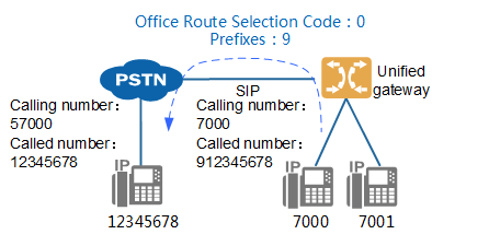
Table 1 Word Crown Description
| Type of word crown | Value | Remarks |
| Numbers | 0, 1, 2, 3, 4, 5, 6, 7, 8, 9 | None. |
| Character | *,#, +
|
* Only in the first and last 1.
# Only in the first and last 1. + Only in the first place. Notice: The prefix of the called word configured for call restriction cannot start with * or. |
| Wildcard | x, which matches any number from 0 to 9. | X cannot be placed at the top of the word to prevent abnormal outgoing calls.
X cannot be placed in []. X and X are the same, not case sensitive. |
| Scope | [], a number in the range of 0 to 9. One or more numbers in the brackets indicate a selection range, and any number that appears in the range can be matched.
For example, [0125] means to match any number in 0,1,2,5 |
[] must come in pairs,[] no more [] inside. [] There must be content in it. The numbers inside [] must appear in ascending order. |
| Subrange | [-], in the word crown, two numbers are connected by a “-” to indicate a range, such as “2-4” to match any number between 2 and 4, including 2 and 4.
It is called a subrange because this structure can only appear in square brackets. For example, “[1-578]” means any match from 1 to 5, or 7 or 8, excluding 6. |
-It can only be in [], and the front and back must be numbers. The front number must be smaller than the back number, that is, [01-34] is legal,[10]/[1]/[]/[-]/[-9]/[3-3]/[3-2] is illegal. |
Provide several examples of word crown analysis for the common word crown, as shown in Table 2.
Table 2 Examples of word crown analysis
| Example of word crown | Meaning |
| [2-8]xxxxxxx | The word crown matches an 8-digit number, the first digit must be 1 of the digits 2-8, and the remaining seven digits can be any 1 of the digits 0-9. |
| 13xxxxxxxxx | The word crown matches an 11-digit number, the first digit must match 1, the second digit must match 3, and the remaining 9 digits match 0 to 9. |
| 1[0124-9]x | The word crown matches a 3-digit number. The first bit must match 1; the second bit matches any 1 bit in 012 or any 1 bit in 4~9, that is to say, as long as the second bit is any number except 3, it can match successfully; The third bit matches any number from 0 to 9. |
The general word crown number analysis table and the precise word crown number analysis table are two separate parts, the unified gateway in the number analysis, first from the precise word crown number analysis table to start the query, if there is a corresponding word crown and the analysis result is a complete match to stop the search, otherwise go to the general word crown number analysis table to find. If there is a perfectly matched wildcard crown in the wildcard crown number analysis table at this time, the perfectly matched wildcard crown is the standard; if there is no perfectly matched wildcard crown, the analysis results of the original exact wildcard crown number analysis table are retained.
When the two common word crowns match, the more accurate match shall prevail, such as 31xx and 310x. If 3100 is dialed, 310x is matched, because 310x contains 10 word crowns and 31xx contains 100 word crowns. When the matching degree is the same (such as 31x 0 and 310x), the sorting result of show prefix shall prevail, and the wild word crown supports both called word crown analysis and calling word crown analysis.
Scenario Description
This section describes the method of word crown configuration to achieve the following requirements as an example.
- Add bureau word crown 7, “type of business” to “basic business”.
- Add out word crown 9, office to select code 0, “business type” for “basic business”, “call attribute” for “local call”.
Notice
In order to prevent illegal calling, the domestic long-distance calling word crown and the international long-distance calling word crown must be added before adding the local calling word crown, otherwise the operation will fail.
Operation steps
1. Configuration bureau word crown
- Log in to the Web management system of the unified gateway. For details about how to log in, see Login to the Web Management System.
- Choose Relay Management> Called Word Crown Configuration. On the Word Crown Configuration page, click Add “.
- Configure the word crown in the “Create word crown” dialog box, as shown in Figure 3.
Figure 3 Configuration Bureau word crown


The key parameters are described in Table 3. For a more complete and detailed description of the parameters, see the Web Management System Online Help.
Table 3 Description of key parameters
| Parameter Name | Parameter Description |
| Word Crown | The character length of the word crown cannot exceed 40 characters, and the real word crown length cannot exceed 32 bits.
For example, if the character length of word crown 3[3-6] is 6, the real word crown length that can be matched is 2 bits. |
| Business Type |
It is used for basic voice services such as intra-office calls and local calls.
A service used to modify or supplement basic voice services.
It is used for special intelligent services such as call waiting and call attendant group.
For virtual user services such as teleconferencing, automatic switchboard, custom VU, etc. |
| Call Properties |
Calls between users under the same unified gateway.
The configured word crown has a local call attribute, select that call attribute.
The configured word crown has a domestic long-distance attribute, and the call attribute is selected.
The configured word crown has the international call attribute, select the call attribute.
When you need to configure an emergency call (such as 119, 110, etc.), select the call attribute.
If the local short number overlaps with the first few digits of the local call, the word crown of the call attribute needs to be configured. When the call attribute routes the call, the in-office user is selected first, and the out-of-office local user is selected after the in-office user selection fails.
When different outgoing dialing methods have the same word crown but different number lengths, select this call attribute. For details, see Configuring Route Analysis Word Crown by Number Length. |
| Calling Number Conversion | Conversion of the number of the calling subscriber. It is mainly used for applications with special requirements, such as showing the same switchboard number for users out of the office.
The priority in the three number conversion methods is: long and short number> number mapping> number conversion. Please refer to Configuring Number Transformation for how to configure. |
| Calling Number Mapping | The user configured with the caller number mapping is displayed as the mapped number when the trombone is not configured.
The priority in the three number conversion methods is: long and short number> number mapping> number conversion. For details about how to configure, see Configuring Number Mapping. |
| Called Number Change | The transformation of the number of the called subscriber. For example, the calling user dials “812345678”, the unified gateway deletes the outgoing word crown “8”, and then sends out the real called number “12345678.
The priority in the three number conversion methods is: long and short number> number mapping> number conversion. Please refer to Configuring Number Transformation for how to configure. |
| Called Number Mapping | The user configured with the called number mapping is displayed as the mapped number when the trombone is not configured.
The priority in the three number conversion methods is: long and short number> number mapping> number conversion. For details about how to configure, see Configuring Number Mapping. |
| Show calling trombone | A trombone is a number configured for a short number user to display when out or call directly by an out-of-office user. The priority in the three number conversion methods is: long and short number> number mapping> number conversion.
The parameter defaults to No “. When the parameter is set to “Yes” and the user has set the trombone number, the calling number is converted to trombone out when the outgoing call is made. |
| Allow PSTN access | Whether to allow relay users to call the word crown.
When the parameter is set to No, the relay user cannot call the number at the beginning of the word crown. |
| User called number type | The type of called number that the office user passes to the PSTN when the call is out through this word crown. |
| User calling number type | The type of calling number that the office user passes to the PSTN when calling out through this word crown. |
| Whether to change the trunk called number type | Whether to change the called number type when the call is out through the word crown. |
| Relay Called Number Type | The type of called number that is transferred to the PSTN when the call is outgoing through this word crown. |
| Change trunk calling number type | Whether to change the calling number type when the call is out through the word crown. |
| Relay Calling Number Type | The type of calling number that is passed to the PSTN when the call is outgoing through the word crown. |
| 32-level custom permissions | It is a 32 kinds of user-defined permissions extended on the basis of 4 kinds of basic call permissions, which can be combined with the call crown permission to restrict the specified user from calling.
For example, the outgoing word crown 9 is configured with 32-level custom attribute custom 1, and the outgoing call permission 7000 to the user is also configured with custom 1 permission, then only the 7000 can be out through the word crown 9. |
Description
- User called number type, user calling number type, whether to change the type of relay called number, whether to change the type of relay called number, whether to change the type of relay calling number, and whether to change the type of relay calling number, which is mainly used to change the type of number to be taken when the main/called number is out through E1 relay (PRI, QSIG) according to the title of the called number. These types include the following: user number, valid domestically, valid internationally, unknown.
- The maximum number length corresponding to the current word crown can be configured when the word crown is added. The default value is 32 digits. To prevent unauthorized users from making phone calls by adding the number prefix, we recommend that you configure the corresponding number length according to different word crown types. The default maximum number length is 32 for intra-office calls, 13 for domestic long-distance calls, 32 for international long-distance calls, and 12 for local calls, local inter-office calls, intra-office or local calls.
d. Click OK “.
2. Configure outgoing word crown
Notice
In order to prevent illegal calling, the domestic long-distance calling word crown and the international long-distance calling word crown must be added before adding the local calling word crown, otherwise the operation will fail.
- On the word crown configuration page, click Add “.
- Configure the word crown in the “Create word crown” dialog box, as shown in Figure 4.
Fig. 4 Configuration Outword Crown

- Click OK “.
Operation result
Log in to the Web management system of the unified gateway, and on the “Relay Management> Called Crowns Configuration” page, query the configured exact crown and wild crown.
Configure SIP Trunk
This section describes how to configure a scenario in which a unified gateway interfaces with peer devices through SIP trunks. When configuring SIP trunks, peer devices must support SIP trunks.
Background information
SIP trunking is the 1 type of packet trunking, which is based on IP bearer and uses an Ethernet cable to interface with the peer device.
Unlike the physical channel defined by circuit trunking, SIP trunking defines a logical channel, which is mainly used to solve the problems of interworking authentication and call addressing between this office and the opposite office.
The SIP transport protocols supported by the unified gateway are as follows:
| signaling transport protocol | Introduction to the Agreement | local transmission port |
| UDP | 1 is a connectionless, unencrypted transport layer protocol that provides simple and unreliable transaction-oriented messaging services. Less resource consumption and fast processing speed, but does not guarantee that the data packet can arrive safely and completely. | 5060 must be used |
| TCP | 1 a connection-oriented, reliable, IP-based, unencrypted transport layer protocol. The processing speed is not as fast as UDP protocol, but it has mechanisms such as packet loss retransmission and data verification to ensure the safe and complete delivery of data packets. | Please use 5060 |
| TLS | 1 is an encrypted transport protocol used to provide secure and complete data transfer between two communicating applications. | Please use 5062 or 5063 |
Only the operation of implementing SIP trunk calls through non-encrypted UDP and TCP protocols is described here. For more secure SIP trunk calls, refer to Configuring Signaling Encryption Configuring SIP Trunk to Encrypt Transport Using the TLS Protocol.
Scenario Description
This section describes how to configure a SIP trunk by taking the following requirements as an example. In actual configuration, please operate according to your data plan.
SIP trunk is configured with the office direction number of 0, the domain name of the counteroffice device of pbx1, the IP address of the counteroffice of 172.16.15.87, UDP transmission protocol is adopted, and the signaling port number of the counteroffice and the local office is 5060.
Operation steps
Log in to the Web management system. For details about how to log in, see Login to the Web management system.
Choose Relay Management> Relay Configuration> SIP “.
In the SIP trunk configuration box, click Add a match “.
The blue icon “new point” is displayed on the interface (representing the matchup device).
Click “new point” or “new point” to connect with this bureau, and set the values of each parameter according to the actual networking situation and interface prompts, as shown in fig. 1.
Figure 1 Configuring a SIP trunk

Description
If you use a TCP port other than 5060 for SIP trunk communication, configure an FPGA throttling policy based on the corresponding transport protocol for the port and set the data transmission throttling threshold to 1000 to prevent traffic attacks on the port.
The key parameters are described in Table 1. For a more complete and detailed description of the parameters, see the Web Management System Online Help.
Table 1 Description of key parameters
| Parameter Name | Parameter Description |
| Domain Name of the Machine | The name of the game device used to uniquely identify it on this device. This parameter must exist and cannot have the same name as other equipment in this bureau. |
| Transport Protocol Type | Transport protocols are divided into UDP, TCP, TLSServer and TLSClient.
Description: When using the TLS protocol to encrypt signaling, the two sides of the transmission can be defined as “TLSServer” and “TLSClient”, respectively “. To configure TLS signaling encryption, see Configuring Signaling Encryption. |
| Bureau to the number | Select the office number of the office where the SIP trunk is located. |
| Maximum limit call number | The maximum number of calls allowed on this SIP trunk. When the total number of incoming and outgoing trunk calls on the SIP trunk exceeds the limit, the system will automatically reject subsequent new calls. |
5. Click OK “.
After completing the SIP trunk configuration, the connection between this office and the opposite office turns gray.
A gray line indicates that the parameter configuration is successful, and a red line indicates that the data is not configured or the configuration fails.
Result validation
| Validation Tasks | Verify Operation | Verification Results |
| Verify Relay Docking | The user of this play dials the user of the game. | Achieve normal calls |
Configure R2 Trunking
This section describes the configuration and implementation of docking between a unified gateway and a peer device through an R2 relay.
Prerequisites
The X1911/X1960/X1981 MTU board has been configured. For details about how to configure the MTU board, see Configuring a Board.
The digital relay cable has been installed to physically connect the bureau and the bureau. For how to install it, please refer to the installation of the digital relay cable in the quick installation guide.
Background information
R2 Relay
R2 relay is the 1 kind of digital circuit relay, which uses E1 trunk to interface with the opposite equipment. It uses R2 signaling as inter-office signaling. R2 signaling is a 1 type of CAS(Channel Associated Signaling), that is, associated signaling. R2 signaling is defined by ITU-T Q.400-Q.490. Since each country or region has its own implementation method, there are multiple versions of R2 signaling in various countries in the world, and there is still a big difference between some versions of associated signaling and standard R2 signaling.
The connection duration range of R2 relay depends on the number length of the calling and called party, and 1-digit numbers are processed every 0.3s. For example, if the length of the calling number is 8 digits and the length of the called number is 10 digits, the subsequent response time is 0.3 *(10+8)= 4S.
clock source
A clock source refers to a device that provides standard time, and devices at both ends of the interface perform clock synchronization based on the clock source. The clock source is configured to prevent the phenomenon of frame slippage (I. e., voice packet loss).
If the unified gateway interfaces with multiple devices through E1/T1 trunks, you only need to configure the clock source of one of the devices, and the unified gateway will synchronize the clock of the device. If the clock is based on the unified gateway, you do not need to configure the clock source.
Scenario Description
This section describes how to configure an R2 relay by taking the following requirements as an example. In actual configuration, please operate according to your data plan.
The associated signaling type is set to China.
Take X1960 as an example, add a link, the link number is 0, use E1 port 0, the office number is 2, and the default called number is 68907000.
Operation steps
Log in to the Web management system. For details about how to log in, see Login to the Web management system.
Configure R2 signaling
- Choose Relay Management> Relay Configuration> R2 “.
- Click Add this office in the R2 trunk configuration box “.
- Click “new local” and set the value of each parameter according to the interface prompt, as shown in Figure 1.
Figure 1 Configuring R2 signaling

- Click OK “.
Configure R2 Trunking
- Click Add matchup in the R2 trunk configuration box “.
- Click new point “.
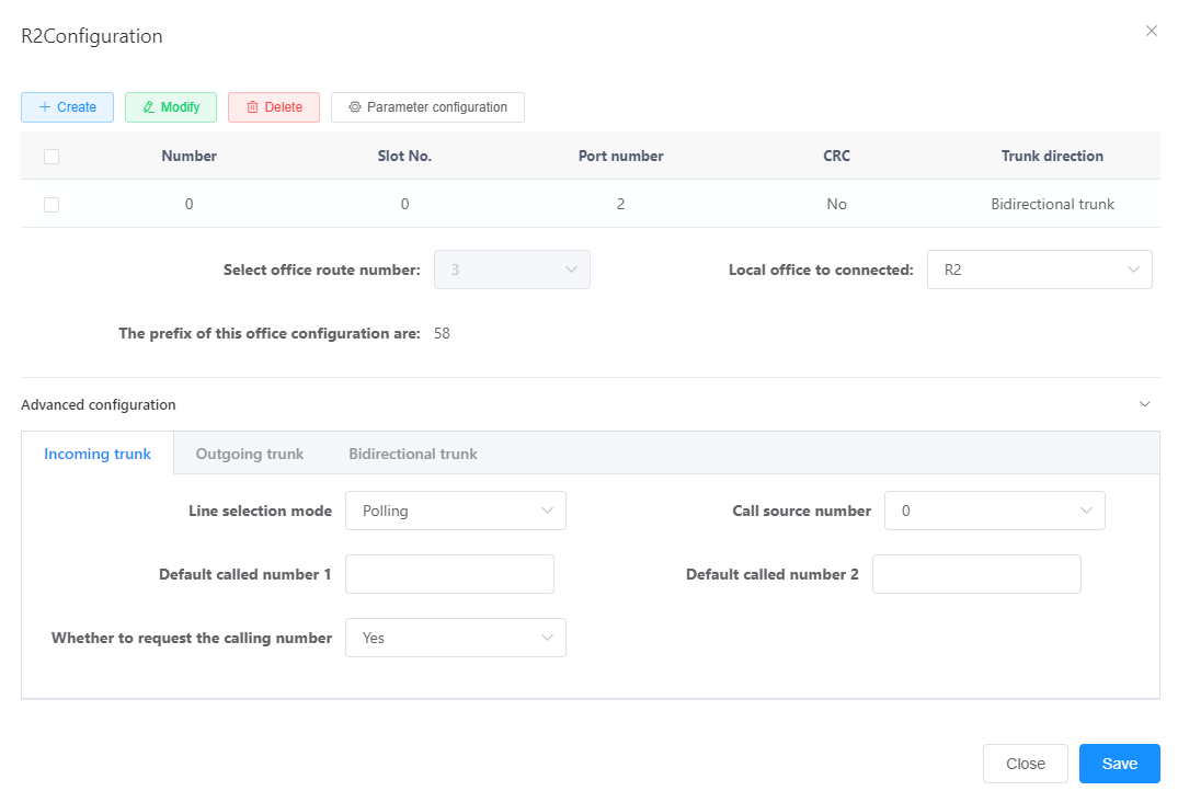
- Set the values of each parameter according to the actual situation and interface prompts, as shown in Figure 2.
Figure 2 Configuring an R2 relay
- Click OK “.
Complete the R2 relay configuration and add a connection between the bureau and the counteroffice, indicating that the parameter configuration is successful.
Result validation
| Validation Tasks | Verify Operation | Verification Results |
| Verify Relay Docking | A user of this bureau calls a user of the bureau | Achieve normal calls |
Configure PRA Trunk
This paper introduces the configuration method of the unified gateway and the peer device through the PRA relay docking scenario, and realizes the docking.
Prerequisites
- The X1911/X1960/X1981 MTU board has been configured. For details about how to configure the MTU board, see Configuring a Board.
- The digital relay cable has been installed to physically connect the bureau and the bureau. For how to install it, please refer to the installation of the digital relay cable in the quick installation guide.
Background information
PRA Relay
PRA(Primary Rate Adaptation) relay is the 1 type of digital circuit relay that uses E1/T1 trunks to interface with peer devices. It uses DSS1(Digital Subscriber Signaling No.1) signaling as control signaling. The DSS1 signaling is designed based on a network side/user side model, that is, one side of the relay must be a network side and the other side must be a user side.
clock source
A clock source refers to a device that provides standard time, and devices at both ends of the interface perform clock synchronization based on the clock source. The clock source is configured to prevent the phenomenon of frame slippage (I. e., voice packet loss).
Scenario Description
This section describes how to configure a PRA relay by taking the following requirements as an example. In actual configuration, please operate according to your data plan.
Take X1960 as an example, add a PRA link, the office direction is 1, the link number is 1, use E1/T1 port 1, and the link location is “user side”.
Operation steps
1. Configure PRA relay data.
- Log in to the Web management system. For details about how to log in, see Login to the Web management system.
- Choose Relay Management> Relay Configuration> PRA “.
Description
By default, the system already has a local “Local”.
- In the PRA Relay Configuration box, click Add a matchup “.
The blue icon “new point” is displayed on the interface (representing the matchup device).
- Click “new point” or “new point” to connect with this bureau.
- In the dialog box that appears, click Create “.
- Set the values of each parameter according to the actual situation and interface prompts, as shown in Figure 1.
Figure 1 Configuring PRA relay
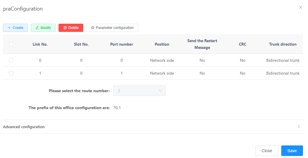
The key parameters are described in Table 1. For a more complete and detailed description of the parameters, see the Web Management System Online Help.
Table 1 Description of key parameters
| Parameter Name | Parameter Description |
| Location | Refers to the location in the PRA link, including “user side” and “network side”. Need to negotiate with the peer, both ends must be set to different values. |
| CRC | 1 is a data verification mechanism that needs to be negotiated and consistent with the peer. If the peer has cyclic redundancy check enabled, this parameter needs to be set to Yes “. |
| Whether to send restart message | Reset message. During the call, when the path state is abnormal, a Restart message needs to be sent to the peer device to restart the program, so that the communication between the two parties can be restored to an available state. |
- Click OK “.
After the PRA relay configuration is completed, the connection between this office and the opposite office turns gray.
A gray line indicates that the parameter configuration is successful, and a red line indicates that the data is not configured or the configuration fails.
2. Configure the clock source. For details, see Configuring a Clock Source.
Result validation
| Validation Tasks | Verify Operation | Verification Results |
| Verify Relay Docking | A user of this bureau calls a user of the bureau | Achieve normal calls |
Configuring QSIG Trunking
This paper introduces the configuration method of the unified gateway and the peer device through the QSIG relay docking scenario, and realizes the docking.
Prerequisites
The X1911/X1960/X1981 MTU board has been configured. For details about how to configure the MTU board, see Configuring a Board.
The digital relay cable has been installed to physically connect the bureau and the bureau. For how to install it, please refer to the installation of the digital relay cable in the quick installation guide.
Background information
QSIG Relay
QSIG relay is the 1 kind of digital circuit relay, which uses E1/T1 trunk to interface with peer equipment. It uses QSIG signaling as control signaling, and QSIG signaling is designed based on a network side/user side model, that is, one side of the relay is a network side, and the other side must be a user side.
clock source
A clock source refers to a device that provides standard time, and devices at both ends of the interface perform clock synchronization based on the clock source. The clock source is configured to prevent the phenomenon of frame slippage (I. e., voice packet loss).
If the unified gateway interfaces with multiple devices through E1/T1 trunks, you only need to configure the clock source of one of the devices, and the unified gateway will synchronize the clock of the device. If the clock is based on the unified gateway, you do not need to configure the clock source.
Scenario Description
This section describes a method for configuring a QSIG relay by taking the following requirements as an example. In actual configuration, please operate according to your data plan.
Take X1960 as an example, add a link, the link number is 1, use E1/T1 port 1, and the link location is “user side”.
Operation steps
1. Log in to the Web management system. For details about how to log in, see Login to the Web management system.
2. Configure QSIG relay data.
a. Choose Relay Management> Relay Configuration> QSIG “.
Description
By default, the system already has a local “Local”.
B. Click Add matchup in the QSIG trunk configuration box “.
The blue icon “point:0” is displayed on the interface (representing the game device).
C. click “point:0” or “point:0” to connect with this bureau.
d. Click Create in the displayed dialog box “.
E. set the values of each parameter in the newly added line according to the actual situation and interface prompts, as shown in fig. 1.
Figure 1 Configuring a QSIG relay
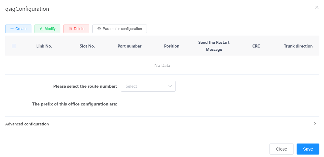
The key parameters are described in Table 1. For a more complete and detailed description of the parameters, see the Web Management System Online Help.
Table 1 Description of key parameters
| Parameter Name | Parameter Description |
| Location | Refers to the location in the QSIG link, including “user side” and “network side”. Need to negotiate with the peer, both ends must be set to different values. |
| CRC | 1 is a data verification mechanism that needs to be negotiated and consistent with the peer. If the peer has cyclic redundancy check enabled, this parameter needs to be set to Yes “. |
| Whether to send restart message | Reset message. During the call, when the path state is abnormal, a Restart message needs to be sent to the peer device to restart the program, so that the communication between the two parties can be restored to an available state. |
f. Click OK “.
After the QSIG relay configuration is completed, the connection between the office and the counteroffice turns gray, indicating that the parameter configuration is successful.
3. Configure the clock source. For details, see Configuring a Clock Source.
Result validation
| Validation Tasks | Verify Operation | Verification Results |
| Verify Relay Docking | A user of this bureau calls a user of the bureau | Achieve normal calls |
Configure SS7 Trunking
There are two typical application scenarios when the unified gateway interfaces with the peer device through the SS7(Signaling System No.7) relay. This section describes the configuration method when voice data and signaling data are not split. Signaling data and voice data are both transmitted to the peer device through the same transmission channel.
Prerequisites
X1911/X>1960/X1981 has been configured with MTU single board. For details about how to configure MTU single board, see Configuring Single Board.
The digital relay cable has been installed to physically connect the bureau and the bureau. For how to install it, please refer to the installation of the digital relay cable in the quick installation guide.
Background information
SS7 Relay
SS7 relay uses No.7 signaling as inter-office signaling. Since ISUP(ISDN User Part) and TUP(Telephone User Part) protocols in No.7 signaling can be used to control inter-office relay circuits, SS7 relay can be divided into ISUP relay and TUP relay. At the physical level, the E1 trunk is used to interface with the peer equipment. On the signaling level, which relay is used for docking with the peer device needs to be negotiated with the peer device. A typical networking is shown in Figure 1.
Figure 1 Typical SS7 relay docking networking
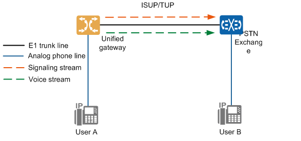
Both signaling data and voice data from the unified gateway are transmitted to the PSTN switch through the E1 trunk.
Description
This section uses ISUP as an example to describe SS7 relay configuration. The configuration of TUP is the same as that of ISUP. You only need to change the ISUP in the script to TUP.
clock source
A clock source refers to a device that provides standard time, and devices at both ends of the interface perform clock synchronization based on the clock source. The clock source is configured to prevent the phenomenon of frame slippage (I. e., voice packet loss).
If the unified gateway interfaces with multiple devices through E1/T1 trunks, you only need to configure the clock source of one of the devices, and the unified gateway will synchronize the clock of the device. If the clock is based on the unified gateway, you do not need to configure the clock source.
Scenario Description
This section describes the SS7 trunk configuration method to achieve the following requirements as an example. In actual configuration, please operate according to your data plan.
Increase the digital relay circuit.
Set the properties of the digital trunk circuit for port 0 in slot 2 of the X1960. Set the office number to 1, the signaling type to ISUP, and the starting CIC to 0.
Add an MTP link to port 0 of the MTU board located in slot 2 of the X1960.
Operation steps
1. Log in to the Web management system. For details about how to log in, see Login to the Web management system.
2. Choose Relay Management> Relay Configuration> SS7 “.
3. In the SS7 relay configuration box, click Add Signaling Point of the Bureau to add signaling points of the Bureau.
4. Add the code of the signaling point of this bureau.
a. Click the Office0 icon.
B. set the values of each parameter according to the actual networking situation and interface prompts, as shown in fig. 2.
Figure 2 Configuration of the Bureau Data
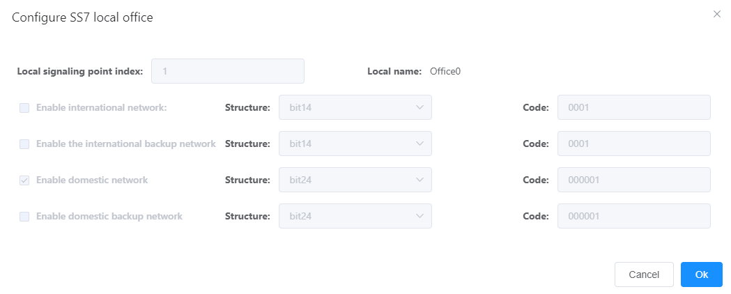
Description
The “structure” and “coding” need to be obtained from the operator.
c. Click OK “.
5. Increase the destination signaling point.
a. Click Add destination signaling point to add a destination signaling point.
B. Click the Point1 icon.
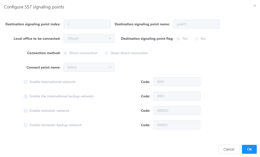
c. Set the value of each parameter according to the actual networking situation and interface prompts, as shown in fig. 3. Where the “code” needs to be obtained from the peer office point.
Figure 3 Configuring signaling transfer point data
d. Click OK “.
6. Increase the digital relay circuit.
a. Click the line between Office0 and Point1.
B. Set the value of each parameter according to the actual networking situation and interface prompts, as shown in fig. 4.
Description
A unified gateway can be configured with up to two MTP links, and each E1 port can be configured with only one MTP link. If an E1 port is not configured with an MTP link, it can share an MTP link with other E1 ports.
Figure 4 Configuring SS7 relay
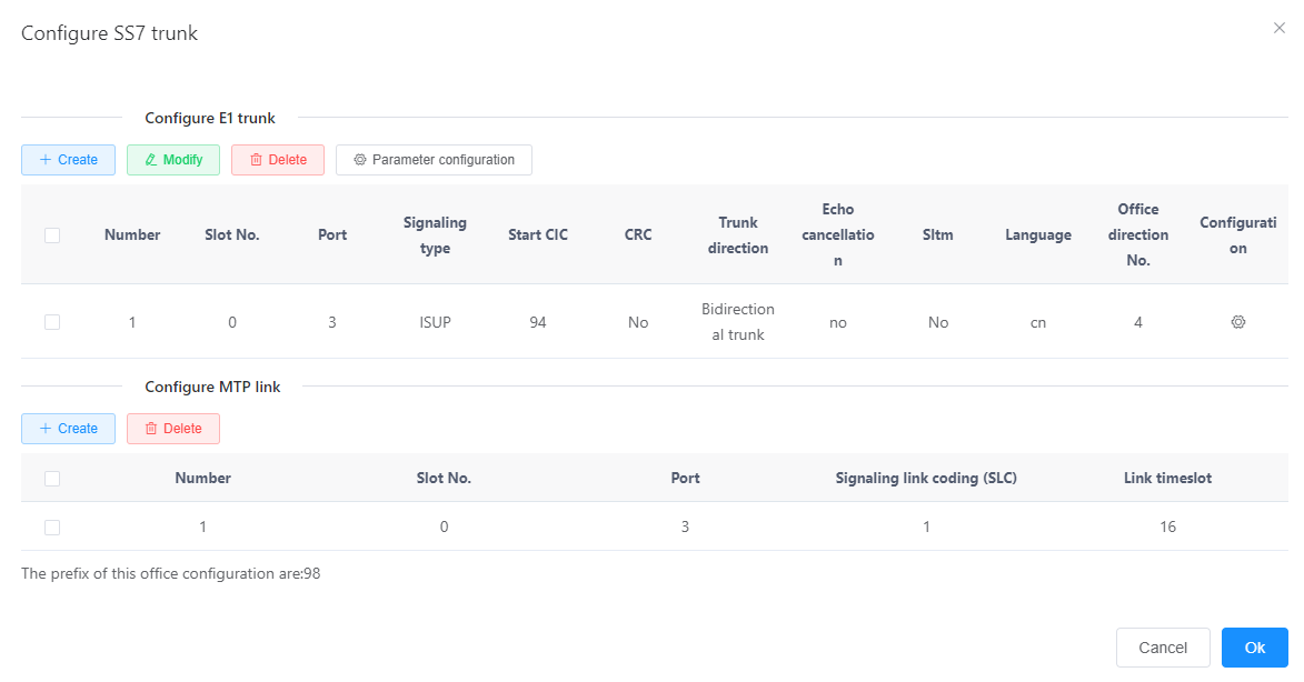
The key parameters are described in Table 1.
Table 1 Description of key parameters
| Parameter Name | Parameter Description |
| Signaling Type | Optional parameters and descriptions are as follows:
ISUP The signaling messages, functions and procedures necessary for the control of circuit-switched services in an integrated services digital network, including voice and non-voice services, are defined. Default value: “ISUP”. |
| Starting CIC | Circuit identification code, used to identify the circuit when the two offices are docked. The CIC codes of the same relay circuit must be completely consistent for successful docking.
Value range: an integer between 0 and 4095. Default value: 0 “. |
| Redundancy Check (CRC) | 1 is a data verification mechanism that needs to be negotiated and consistent with the peer. If the peer has cyclic redundancy check enabled, this parameter needs to be set to Yes “. |
| link slot | The circuit number of the signaling link, which specifies the time slot in E1/T1 for the PRA link.
When the transmission mode is E1, the value of this parameter can only be 16. |
Click the connection between Office0 and point1, and click Settings in the displayed page.
The system pops up the SS7 relay configuration interface, and sets the values of each parameter according to the actual networking situation and interface prompts, as shown in Figure 5.
a. Click OK”
The SS7 relay configuration is completed, and the connection between this bureau and the opposite bureau is added, indicating that the parameter configuration is successful.
Result validation
| Validation Tasks | Verify Operation | Verification Results |
| Verify Relay Docking | A user of this bureau calls a user of the bureau | Achieve normal calls |
Configure AT0 Relay
This paper introduces the configuration method of the unified gateway and the peer device through the AT0 relay docking scenario, and realizes the docking.
Background information
AT0 relay is the 1 kind of analog circuit relay, using analog subscriber line to connect the FXO port of the bureau and the FXS port of the superior bureau, which can realize the function of dedicated line. The networking is shown in Figure 1.
Figure 1 AT0 relay networking
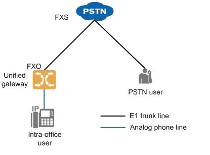
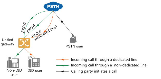
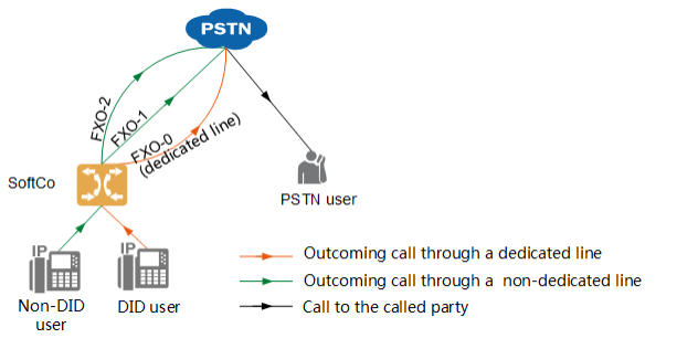
according to the needs of incoming and outgoing concurrent calls, multiple lines can be requested from the local operator, who will assign a number to each line. According to the different policies for the use of these line resources, the office users can be divided into direct dial users (exclusive line) and non-direct dial users. Table 1 shows the routing rules in an incoming and outgoing call scenario.
Table 1 AT0 relay line selection rules
| Incoming and Outcoming Scenarios | Route selection rules |
| PSTN side user incoming call | Line selection rules are shown in Figure 2. The calling party can dial the PSTN number corresponding to the dedicated line to directly call the direct dial user in the office, or dial the PSTN number of the other lines to call any in-office user through the automatic switchboard.
Figure 2 Inroute selection rules for incoming calls
|
| Intra-office user outgoing call | Direct dial users must go out through their own dedicated line when calling out. When a non-direct dial user calls out, the system allocates a line out of the other lines according to the set line selection rules. Line selection rules are shown in Figure 3.
Figure 3 Outgoing Call Route Selection Rules
Optional routing rules for non-direct dial users to call out include:
Select the line from the smallest circuit number until the free available circuit is selected.
Select the line from the largest circuit number until the free available circuit is selected.
Line selection starts from the next circuit of the selected circuit when AT0 is out last time (circuit number increases, and starts from FXO-0 again when the FXO-11 is exceeded) until the idle available circuit is selected. |
Since various countries and regions adopt different AT0 parameter standards (mainly related to signal tone, impedance and caller ID signal mode), these parameters need to be debugged when configuring AT0 relay to avoid problems such as call failure and poor voice quality. <%X%>1911/<%X%>1960/<%X%>1981 the AT0 signal sound and impedance parameter standard values (default is China) of China, Australia, Brazil, Britain, France, Germany, Ireland, Italy, Malaysia, Mexico, New Zealand, Russia, Saudi Arabia, UAE and other countries or regions are preset when leaving the factory, the system ATO parameters can be switched to the standards of these countries or regions. If the office is located in other countries or regions, please refer to the customized AT0 interface parameters to complete the inspection and debugging of specific parameters.
Notice
AT0 relay calls tend to cause more noise interference because the device is not grounded or the grounding effect is not good. In order to improve the quality of the call, the equipment should be well grounded. Refer to the grounding instruction for specific grounding operation and inspection method.
Scenario Description
This section describes how to configure an AT0 relay by taking the following requirements as an example. In actual configuration, please operate according to your data plan.
- The user on the PSTN side can call the automatic switchboard 8888 by dialing the PSTN number corresponding to the FXO-1 line and the FXO-2 line, and can call the user in the office by dialing the extension number according to the voice prompt.
- The user on the PSTN side can directly call the office direct dial user 7000 by dialing the PSTN number corresponding to the FXO-0 line.
Assume that you have done the following:
- The OSU board has been configured. For details, see Configuring a Board.
- The user number 7000 has been configured. For the configuration method, see SIP User Number.
- The automatic switchboard number 8888 has been configured. For details, see Product Documentation> Configuration> Feature Guide> Automatic switchboard “.
- The office direction number 1 has been configured. For details, see Configuring Office Directions.
Configure AT0 Relay
1. Log in to the Web management system. For details about how to log in, see Login to the Web management system.
2. Choose Relay Management> Relay Configuration> AT0 “.
a. Click on the matchup or the connection with this bureau.
B. Click Create in the AT0 Relay Configuration area and set the parameters as shown in Figure 4.
Figure 4 Configuring the AT0 relay

Description
Click the input box in the Port Number column to bind multiple FXO ports to the same office direction. If you configure multiple lines of FXO to bind to the same office direction, you must use the same routing mode and default called number.
c. Click Create in the AT0 Leased Line Configuration area, and set the parameters as shown in Figure 5.
Figure 5 Configuring AT0 leased line

Description
For the same FXO port, at least one of the default called number and the dedicated line number needs to be configured. If both parameters are configured, the line number takes precedence.
d. Click Save to complete the configuration.
e. Click Cancel to close the current pop-up window.
3.(Optional) Configure the AT0 interface parameters.
If the location of the local office belongs to a preset country or region (China, Australia, Brazil, Britain, France, Germany, Ireland, Italy, Malaysia, Mexico, New Zealand, Russia, Saudi Arabia, UAE), please select the corresponding country or region as follows, and the signal tone and impedance parameters of the system will automatically switch to the local standard values.
B if the location of the office is in another country or region, or more AT0 interface parameters need to be modified manually, please refer to customizing AT0 interface parameters to complete the debugging of specific parameters.
4.(Optional) Automatically add# for calls that SIP users are trunked out through AT0.
When a SIP user exits via an AT0 relay, the called number sent to the counterparty does not have a# number by default. If the counterparty requires# as the end sign to complete dialing, the counterparty will wait until the timeout before starting the call. To set a timeout without waiting, follow these steps.
a. Choose Relay Management> Relay Configuration> AT0> Line Parameter Configuration “.
Figure 7 Configuring AT0 Outgoing Automatically Add# for SIP Users
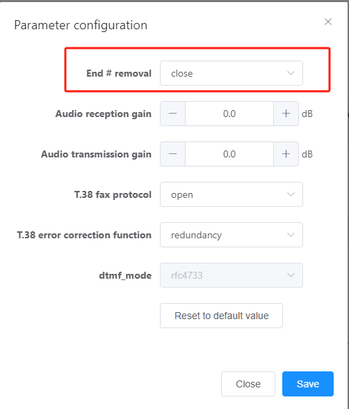
B. Set End# Removal to Off “.
Result validation
| Validation Tasks | Verify Operation | Verification Results |
| Verify Outgoing Call | This office user dials the PSTN side user number. | Achieve normal calls. |
| Verify AT0 Leased Line Functionality | The user on the PSTN side dials the number corresponding to the FXO-0. | The user in the office 7000 ringing. |
| Verify AT0 switchboard functionality | The user on the PSTN side dials the number corresponding to the FXO-1 and the FXO-2. | The calling party listens to the sound of the automatic switchboard number 8888. |

