UC120/UC200/UC1000 User manual

Open Source Communications Ltd.
UC120/UC200/UC1000 Series User’s Manual
Version 1.0

Open Source Communications Ltd.
Address: Room 624, 6/F, Qinghua Information Port, Book Building, Qingxiang Road, Longhua Street, Longhua District, Shenzhen, China 518109
Tel: +86-755-66630978, 82535461, 82535362
Email: Business: [email protected]
Technical support: [email protected]
Working hours: Monday to Friday 09:00-18:00 (GMT+8), except for holidays.
Thanks for choosing OpenVox products!
This document is copyrighted by Shenzhen Open Source Communication Co., Ltd. (OpenVox) all, without permission, the pictures and text in this document shall not be copied, reproduced for commercial purposes. All interpretation rights belong to Shenzhen Open Source Communication Co.
revision history
| version number | Release Date | descriptive |
| 1.0 | 28/11/2023 | First release of Chinese version |
Directory
1.Product Overview
1.1 Product Description
The UC200 series is equipped with up to 8 analog ports and 3 Ethernet interfaces for seamless connectivity with VoIP trunks and existing PSTNs. In addition, the UC200 supports a range of coding and signaling protocols including G711 (alaw/ulaw), G722, OPUS, G726, G729, GSM, iLBC, H264, VP8. The UC200 series supports the industry-standard SIP protocol (sip trunks and sip extensions), analog PSTN trunks and analog handsets.
UC200 series IPPBX products are multi-functional business office telephone systems tailored for branch offices or service departments of small and medium-sized enterprises. This series of products integrates the functions of VoIP, voice, fax and recording, and is compatible with a variety of business platforms and terminals, providing you with a variety of converged communication solutions.
Not only that, UC200 series adopts easy and friendly web-based interface and open MQTT API interface protocol, which allows users to interface with UC200 devices through third-party programs to realize call control interaction and facilitate user management and maintenance. In terms of hardware design, it has a compact structural design. The device is characterized by quick installation, easy deployment and high reliability, which brings a brand-new experience of office and communication for enterprises.
1.2 Product appearance
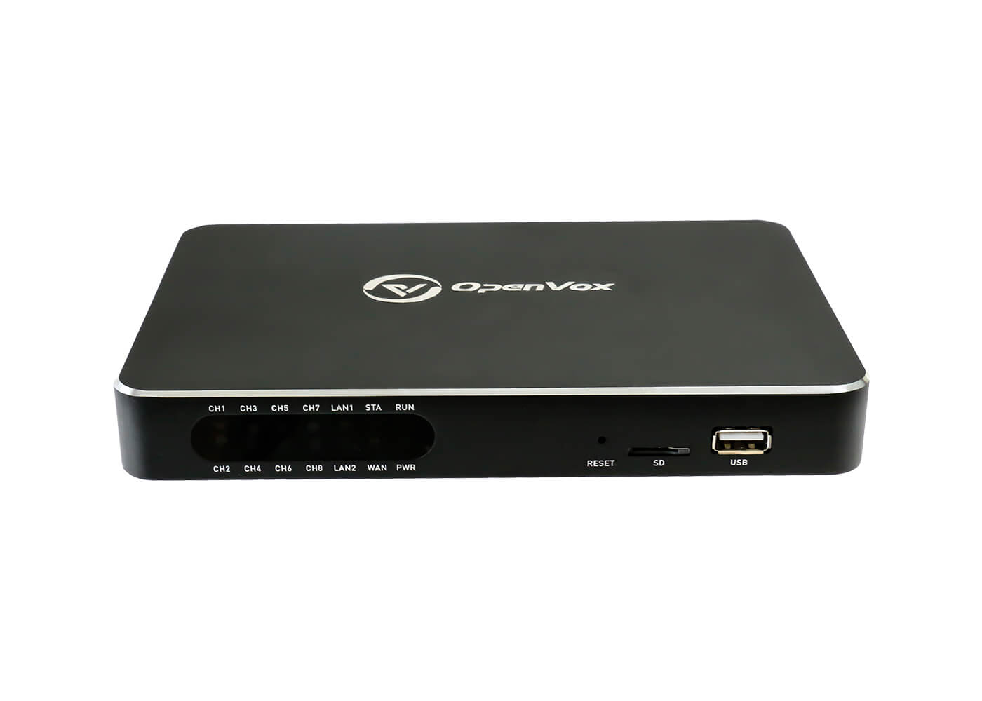
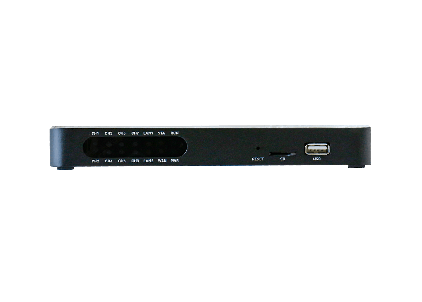
Front Panel Diagram.
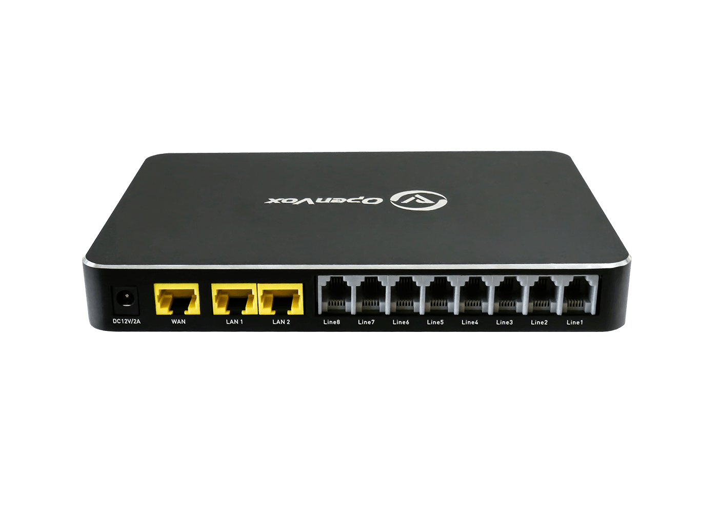
Rear Panel Diagram.
1.3 Front and rear panel interface description
| Front Panel Description | Rear Panel Description | ||
| identifier | clarification | identifier | clarification |
| PWR | Power indicator | DC12V/2A | Power input port, input 12V/2A, maximum power 75W |
| STA | Equipment operation status indicator | RESET | Device reset button |
| Line1-Line8 | 8 RJ11 ports | SD | SD Card Expanded Storage Interface |
| WAN | WAN Port | USB | USB Recording Storage Interface |
| LAN1 | LAN1 network port, usually used for connecting to a local area network (LAN) | LAN2 | Typically interfaces to IMS network ports |
1.4 Indicator light descriptions
| indicator light | define | state of affairs | descriptive |
| Power | Power indicator | resounding | Equipment power-up |
| go out (of a fire etc) | No power to the equipment. | ||
| Run | Equipment operation status indicator | slow blink | Equipment in working order |
| flicker | Device enters safe mode | ||
| Out or no blinking | The device is not in operation | ||
| Flashing status operated in conjunction with the reset button | Refer to Reset Button Operating Instructions | ||
| LAN2 | IMS Network Port Indicator | go out (of a fire etc) | The network is not connected or the network connection is not working properly |
| flash out | The network connection is working. | ||
| WAN/LAN1 | WAN/LAN indicator | go out (of a fire etc) | The network is not connected or the network connection is not working properly |
| flash out | The network connection is working. |
1.5 Reset Button Operating Instructions
| operation number | Reset button operation | Functional Description | Description of the status light blinking process | note |
| 1 | During the operation of the equipment, long press the reset button for 3 seconds, the indicator light blinking frequency change or buzzer drop call, and then release the | The device’s network configuration and web management page passwords are restored to factory settings | Indicator light changes from slow flash to fast flash, at this time, release the button, after a period of time, the running light goes out, the device begins to restart | Just press and hold for more than 3 seconds and observe the first change in the frequency of the status light blinking off. |
| 2 | During the operation of the equipment, press and hold the reset button for 12 seconds, the indicator light flashes the second change in frequency or the buzzer beeps for the second time, and then release the | All configurations of the device are restored to factory settings | Indicator light from slow flash to fast flash, and then to more rapid flash, at this time, release the button, after a period of time, the running light off, the device began to reboot | Just press and hold for more than 10 seconds and observe a change in the frequency of the second status light flash. |
| 3 | Press and hold the reset button for 20 seconds, the indicator light blinking frequency changes and eventually returns to slow blinking (running state), and then release the | Evasive action in case the operator wants to abandon the operation or misuse it during operation | The indicator light changes from a slow flash to a fast flash, then to a faster flash, and finally to a slow flash again, at which point the device does not perform any operation when the button is released | Press and hold for more than 20 seconds |
1.6 Description of models
* N: indicates no support; D: no standing stock, order production required
1.7 Functions and Features
1.7.1 Physical properties
| power wastage | Maximum 20W | electricity supply | 12V/2A DC |
| network interface | 3 (10/100/1000 Base-T) RJ45 | SD card | 1 |
| Analog telephone interface (max.) | 8 (FXS/FXO optional) | USB | 1 |
| power wastage | Maximum 20 watts | ||
| system capacity | Maximum 300 extensions
G.729 15 Concurrent G.711 30 Concurrent |
||
| W/D/H | 188mm*128mm*25mm | ||
| operating temperature | Temperature 0~40℃ Relative humidity 20%~90% non-condensing | ||
| net weight | 0.55Kg | ||
1.7.2 Main characteristics
- Single device provides 8-way FXS/FXO channel access method
- Flexible call routing, based on time, number, source, IP and other routing policies
- Extension user rights management
- Support multi-level IVR, user can customize IVR voice
- API supporting flexible MQTT protocol, providing billing authentication, parameter management, call control, etc.
- Built-in softswitch (IP-PBX) function, support 300 SIP extensions and 30 concurrent calls
- Support for remote management
- Supports multi-terminal registration of a single extension account
- Fax-to-Email Application
- Voicemail support
- Support windows shared network disk recording
1.7.3 Speech Characterization
- VoIP protocols supported: SIP over UDP/TCP/TLS, SDP, RTP/SRTP, WebRTC
- Voice coding support: G711 (alaw/ulaw), G722, OPUS, G726, G729, GSM, iLBC, H264, VP8
- Supports Comfort Noise Generation (CNG)
- Support for Voice Activity Detection (VAD)
- Holds echo cancellation (G.168), 128ms max.
- Support for adaptive dynamic buffering (JB)
- Supports adjustable gain control
- Support for call progress tones: dial tone, ringback tone, busy tone
- Supports NAT penetration
- DTMF mode: RFC2833/SIPINFO/Inband
- Tear-off mode supports busy tone detection and reverse pole detection, answer mode supports delay and reverse pole detection
1.7.4 IPPBX Features
- Supports local storage expansion with TF(Micro SD) card interface and USB interface.
- Support call recording function, recordings can be stored to local storage, can also be stored in the extended network disk space, easy to realize the large capacity storage.
- Supports intelligent inbound routing, which can be routed to different destinations according to different callers and different call times. Support to set the destination address as hang-up, internal extension, extension number, tone, trunk, voice navigation, queue, ringing group, conference call, broadcast, DISA, etc.
- Supports multi-level voice navigation and bilingual navigation in English and Chinese.
- Support extension ringtone function, each extension can be set independently of the incoming color ringtone.
- Support call forwarding, call secretary function.
- Support call forwarding function.
- Supports call interception, same group interception and specified interception.
- Supports multi-party calling and teleconferencing.
- Support alarm clock function, you can customize the alarm tone.
- Support broadcast function, support auto broadcast, support auto answer.
- It supports inbound routing and outbound routing management, and provides multiple settings such as priority, time rule, call source, caller-caller number matching, number change, and destination.
- Supports internal and external grouping, speed dialing, extension roaming, call following, call parking, call waiting, call back in case of busy, call logging, billing authentication, fax, voicemail, message-to-email, do not disturb, extension hotline, password lock, extension roaming, call duration limitation, call breaking, call insertion, call monitoring, and secret message monitoring.
- Support security center, built-in firewall, SIP automatic defense, WEB automatic defense, IP registration address restriction, user agent registration restriction, SRTP voice encryption, TLS signaling encryption, prohibit being PING, WAN port access management.
- Supports WEB management in English and Chinese, and prompt voice packs in English and Chinese.
- WebRTC client support
1.7 .5 Managing Maintenance
- Web Management Configuration Interface
- Configuration backup/restore
- Firmware upgrade: support web upgrade
- Bill Inquiry and Export
- System Log Export
- Built-in analog port recording tool and network debugging tool
2 Login
2.1.1 Description of the model
- Connect the LAN1 port of the device to the computer via a network cable, and the computer will obtain an IP address automatically.
- The analog phone is connected to any FXS port and dials *159, or you can query the IP address of the LAN port.
- Open a browser on your computer (google chrome is recommended) and enter the IP address queried by the device. the default address for the LAN1 port is 172.16.101.1.
- Enter your username and password and click Login to enter the administration page. Default user name admin, default password admin.
2.1.2 Management via WAN port
- Connect the WAN port of the device to the company’s intranet via a network cable, and the UC200 will automatically obtain an IP address.
- Access any FXS port through an analog phone, dial *158, and also query the IP address of the WAN port.
- Open a browser (google chrome is recommended) on a computer on the company’s intranet and enter the IP address that the device looks up.
- Enter your username and password and click Login to enter the administration page. Default user name admin, default password admin.
Note: The device is recommended to be installed in the LAN and the default port and password should be changed. Avoid exposing the device to the Internet as much as possible, and you must set up the firewall policy of the enterprise router and the relevant defense functions of the IPPBX Security Center to reduce the risk of Internet attacks.
2.1.3 Logging in to the IPPBX Web Page
The default login account is admin and the default login password is admin.
The default configuration state of the device applies only within the intranet security environment. When the device is exposed to the extranet, or when there is a security risk on the intranet:
- Please consult the instructions in the System -> Security section first to configure the security policy.
- When using SIP extensions, please first review the contents of the instructions in the Extension -> SIP Extension chapter and refer to the Security Precautions to configure the security policy.
- When using SIP trunks, please first review the contents of the instructions in the Trunk -> SIP Trunk chapter and refer to the Security Precautions to configure the security policy.

2.1.4 Change login password
After logging in to the IPPBX page, be sure to change the login password.
Go to System->Administration to change the login password. A mix of special characters + case + numbers is recommended, and the number of password digits is greater than 8.
2.1.5 Automatic WEB defense
Go to System -> Security -> Web Auto Defense. Turn on WEB Auto Defense.
When WEB Auto Defense is enabled, logging in to IPPBX webpage with more than a limited number of password errors will lock the IP address of the logged-in user, making it impossible to continue logging in.
2.2 Configuration Wizard
This section describes several common ways to configure the UC200 series.
2.2.1 Registering as a gateway to a server
UC200 series as a whole registered to the server

2.2.2 Registration of other end devices to UC200
This mode is to use UC200 as IPPBX, first add extension account in UC200 Web page “Extension” -> “SIP Extension”, then configure registered account and registered address on terminal equipment.

2.2.3 Mapping to PBX in Trunk Mode

3 State
The submenus included under the Status menu are Overview, PBX Status, and Real-Time Information, which mainly display information related to the device.
3.1 Overview
IPPBX system information: [Host Model], [Serial Number] [Number of Analog Extensions], [Number of Analog Trunks], [Maximum Allowable Number of SIP Extensions], [Maximum Allowable Number of SIP Trunks], [Firmware Version], [Local Time], [Allowable Time], [Load Average].

IPPBX memory information: [number of available], [number of free], [to buffer]

IPPBX network interface information: [WAN status], [LAN1 status], [LAN2 (IMS) status]

3.2 PBX Status
Real-time display of status, channel call status and IPPBX concurrency status
[Status]

[Live call]

[Number of concurrences]

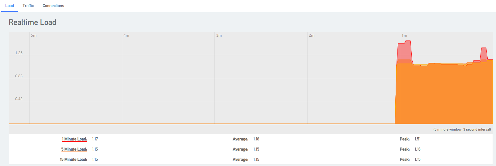
3.3 Real-time information
View CPU load conditions, network traffic conditions, and currently active network links.
[Load]
[Traffic]

[Connections]

4 Networks
4.1 Network interfaces
4.1.1 Overview of the network
After logging into the IPPBX web page for the first time with the factory IP address, you need to change the network configuration of the IPPBX according to the network environment where the IPPBX is located.
- network interface
The system has three interfaces by default, an IMS port, a LAN port and a WAN port, the IMS interface is similar to the WAN port is mainly used to dock the IMS private network, WAN according to their own environment to fill in the data, you can allow the device to connect to the network, LAN port is mainly used for other devices to connect to access.
After opening Network -> Interfaces, you can see the status information of the IMS port, LAN port and WAN port created by default.

- IP address allocation
The IPPBX supports three types of IP address assignment:
[Assign Static IP Address]: Contact your administrator to assign an IP address to the IPPBX. Then you can manually configure IP information on the IPPBX, such as IP address, subnet mask, default gateway and DNS server.
[Obtain IP address from DHCP server]: IPPBX automatically obtains an IP address from a DHCP server after startup.
Note: The IPPBX may assign a different IP address each time it reboots.
[Get IP address from PPPoE client]: Users can connect IPPBX to PPPoE client and then set up PPPoE connection on IPPBX to get IP address.
Note: The IPPBX may assign a different IP address each time it reboots.
4.1.2 Configuring a static IP address
This section describes how to configure a static IP address for the IPPBX.
- Go to Network -> Interfaces.
- Click [Edit] on the default LAN interface or WAN interface.
- In the Protocol field, select [Static Address] and fill in the following network information.

- IPV4 Address: fill in the IP address assigned to the IPPBX.
- IPV4 Subnet Mask: Fill in the subnet mask.
- IPV4 Gateway: fill in the gateway address.
- IPV4 Broadcast: Settings are required when using the broadcast function.
- DNS servers: fill in the domain name resolution server address (usually the same as the IPV4 gateway address)
4 Click [Save & Apply].
4.1.3 Obtaining an IP address from a DHCP server
- Go to Network -> Interfaces.
- Click [Edit] on the default LAN interface or WAN interface.
- In the Protocol field, select [DHCP Client] and fill in the following network information.

4.Click [Save & Apply].
Note: Users can query the IP address by dialing *158 from an extension.
4.1.4 Configuring a PPPoE Network Connection
This article describes how to configure a PPPoE connection on an IPPBX to obtain an IP address.
Configuration scenarios:
The PPPoE client assigns a dynamic IP address to the IPPBX. this article takes the WAN port configuration of PPPoE as an example.
Configuration example:
Select PPPoE for the WAN port and fill in the user name and password.
- [UserName]: Fill in the user name provided by the operator.
- [Password]: Fill in the password provided by the operator.
- Other settings are filled in according to the operator’s requirements.
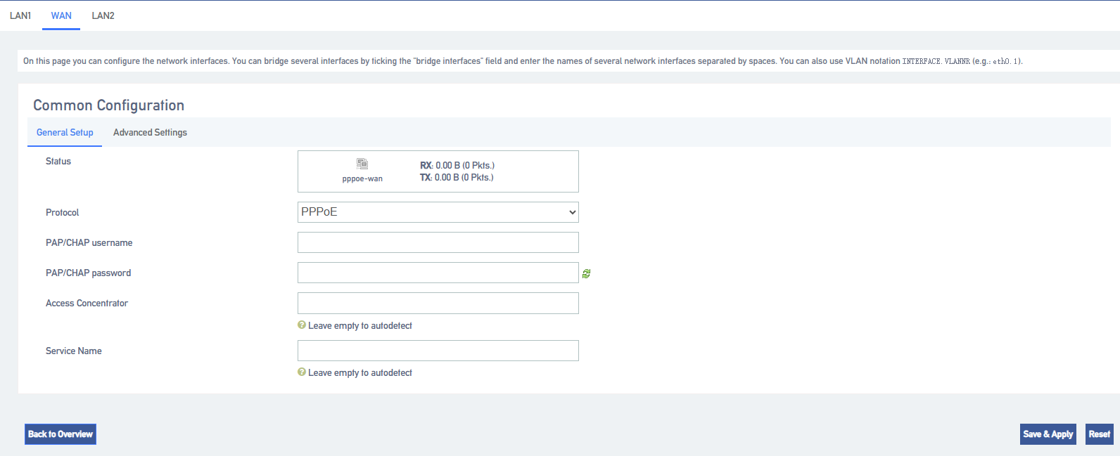
Click [Save & Apply]: to make the configuration take effect.
4.2 DHCP/DNS
4.2.1 Basic configuration
The LAN interface controls a segment of the IP address range when connecting to a network device, allowing the network device to automatically obtain the IP address and subnet mask assigned by the server.
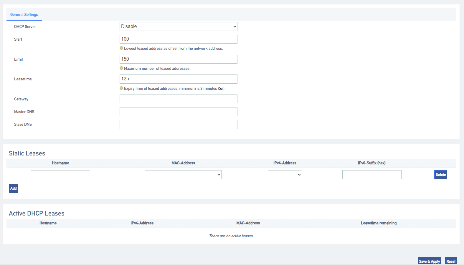
4.3 Hostname
4.3.1 Hostname Configuration
A hostname contains a mapping between IP addresses and hostnames, and also includes aliases for hostnames. In the absence of a domain name server, all network programs on the system resolve the IP address corresponding to a given hostname by querying this file; otherwise, a DNS service program is required to resolve it. Commonly used domain names and IP address mappings can usually be added to the hosts file for quick and easy access.
Note: IMS docking is ensured by configuring the domain name and IP address relationship when certain IMS relay domain names cannot be interpreted.
4.4 Static routes
4.4.1 Adding static routes
Static routing allows a specific IP or domain name to communicate data through a specified network port. If not configured, data communication occurs through the default network port.
- Go to Network -> Routes -> Static Routes and add a static route.
- Configure the routing entries according to the following list.
[Interface]: select the network interface. the IPPBX will reach the destination IP through this interface and this static route.
[Target Host IP or Network]: Enter the destination IP address. the IPPBX will reach the destination IP through this static route.
[Subnet Mask]: Enter the destination subnet mask.
[Gateway]: Enter the gateway address of the destination IP.
[Leap Points]: Optional. Leap points are used to determine the best path to reach the destination IP.
[MTU]: Set the MTU.
Click [Save & Apply].
4.4.2 Static Route Configuration Example IMS Private Line
If the SIP trunk provided by the operator is an IMS leased line, this IMS leased line can only be used in the network environment specified by the operator. In order to ensure the normal use of the IMS leased line, the user needs to add static routes and configure NAT and firewall.
- Network Configuration
- Before configuration, you need to know that the local router connects to the WAN port of the IPPBX; the SIP carrier router connects to the IMS port of the IPPBX.
- Log in to the IPPBX webpage and go to Network->interfaces to configure the network of IPPBX.
- Default interface: select WAN.
- In the WAN menu bar, configure the WAN port with the protocol set to DCHP Client.
- On the IMS port, the protocol is set to Static Address Matching, and the network information provided by the operator is filled in.
- Click [Save & Apply].
- Static Route Configuration
- Log in to the IPPBX webpage, go to Network -> Routes –> Static Routes, and click [Add].
- Set up routing rules for SIP trunks to route SIP trunks to the carrier’s routers.
[Interface]: Select the IMS port.
[Object Host IP or Network]: Enter the IP address of the SIP trunk.
[Subnet Mask]: Enter the subnet mask of the SIP trunk.
[Gateway]: Enter the gateway IP of the IMS port.
[Leap Points]: Leave blank.
[MTU]: Set the MTU.
- Firewall Configuration
Users who have set up a firewall may cause the SIP private line, to be intercepted accidentally. Users need to add a new firewall to ensure that the SIP trunk can be used normally.
- Go to System->Security Center->Firewall Rules and click [Add].
- Configure firewall rules so that SIP trunks can receive data normally.
[Name]: Set the rule name.
[Action]: Choose to accept.
[Agreement]: Select BOTH.
[Type]: Select IP.
[Source IP Address/Subnet Mask]: Fill in the IP segment of the SIP trunk. In this example, fill in 222.6.99.0/255.255.255.0.
【Port】: Leave it blank, there is no blocking restriction on the port.
3.Click [Save & Apply]
5 Extensions
5.1 Analog extensions
This article will give users a detailed explanation of the function settings of the analog extension
5.1.1 Analog Extension Basic Settings
Path: “Extension” -> “FXS”, select an analog extension, and click [Edit] to go to the [General Settings] page of the analog extension.
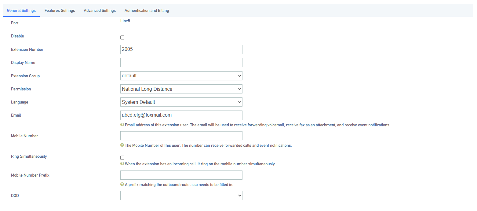
Setting parameters.
| set up | clarification |
| prohibit the use of sth. | A reboot of the device is required after enabling to take effect. Disabled analog extensions cannot make and receive calls. |
| (telephone) extension | The extension number used to make and receive calls. |
| Display Name | The name of the caller that the other party will see when this user makes a call. Only IP Phones or SIP Softphones can display this. |
| subassemblies | Grouping of extensions. |
| scope of one’s jurisdiction | Permission setting when an extension makes a call, there will be permission restriction when the extension makes a call to an outside line, if the permission of the extension does not meet the permission of the outside line, it will not be able to make an outgoing call.
|
| multilingualism | The language category of the prompt tone played by the system. Supports Chinese voice and English voice. |
| DOD port | Bound outside line port, this extension can directly call out to the outside world through the bound outside line port, no need to take the call out routing out of the office. |
| Fill in the user’s e-mail address. (This function is used to receive voice messages and fax Tiff files) |
5.1.2 Analog Extension Features Settings
- voicemail
When users are on a call or have other important matters that make it impossible to answer the incoming call, they can enable the voice mailbox function. When it is turned on, when the caller can not be connected, the caller will hear a message tone, and after listening to it, he/she can leave a voice message. After the message is finished, users can press *2 to listen to the message according to the operation prompts. The configuration is as follows:
Setting Path: “Extension” -> “FXS”, select an analog extension and click [Edit] to go to the [Features Settings] page of the analog extension.
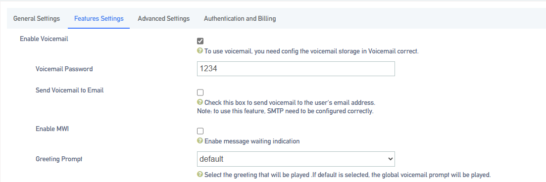
Setting parameters.
| set up | clarification | |
| Send a voice message to your mailbox | When enabled, you need to fill in the e-mail address. The message file received by the extension will be sent to the filled mailbox. | |
| Voicemail Password | The password that needs to be filled in when the user dials *2 or *02 to access the message menu after setting the password. | |
| Message Reminder | The message tone that will be heard when the other party calls and cannot be reached. | |
| default (setting) | System default tone. | |
| import speech | Imported into the IPPBX internal beeps. | |
| self-record | Currently record your own cues. | |
- Login/Logout
Click “Extension” -> “FXS” -> “General Settings” and find the [Login/Logout] function.
- Login: When you select Login, you can dial the number normally.
- Logout: When you select Logout, you will not be able to make calls. However, the feature code will still work normally. (Default *105 login, *106 logout)
- distraction-free
Users who don’t want to be disturbed can automatically reject calls when they enable Do Not Disturb.
Setting Path: Click Extension -> FXS -> Features Settings, and find the Do Not Disturb function as follows.

Setting parameters:
| set up | clarification |
| cloture | Turn off Do Not Disturb mode. |
| normally open | It’s in do-not-disturb mode and no calls can come in. |
| appointed time | In no-disturb mode for a set period of time.
Example: The time period is 8:30-12:30.During this time period, no incoming calls will be received. |
| Applications:
*78, enable do not disturb. *79, cancel the do-not-disturb. Attention: After scrambling is turned on, any incoming calls, including ringing groups, IVRs, queues, etc., cannot be connected (except for broadcast groups). |
|
- secretarial extension
When an extension receives an incoming call, it transfers the call to the designated extension, which is the secretary extension.
Set the path:
Extension -> FXS -> Features Settings. The content is as follows

Setting parameters:
| set up | instructions |
| secretarial extension | Select a number to bind to as a secretarial extension. |
| Insider to Secretary | The secretary extension can only be transferred when the device is called from inside the device. |
| Outside to Secretary | It can only be transferred to the secretary’s extension when an outside line is called in. |
- conditionality transfer
Conditional transfer is a very useful feature that can be done when the user is unable to answer an incoming call, or is in the middle of a call, or doesn’t have time to answer an incoming call.
Set the path:
Click Extension -> FXS -> Features Settings and find Conditional Transfer as follows.

Setting parameters:
| unconditional transfer | All incoming calls are transferred to the specified destination. | |
| move quickly in an emergency | When in occupancy, incoming calls are transferred to the specified destination. | |
| No answer transfer | When a call is not answered, the call is transferred to the specified destination. | |
| Unconditional, busy, no-answer transferable destination | cloture | The unconditional transfer feature is off, by default. |
| leave a message | Transfer to voicemail. | |
| (telephone) extension | Transfer to the specified extension. | |
| repeat | Go to the designated outgoing number. | |
- monitor
When a user has listening privileges, he or she can listen to other users’ calls by pressing [Listening Feature Code] + [Extension Number to Listen] on the handset.
Set the path:
Go to Extension -> FXS -> Features Settings and find the Secretary Listening function as follows.

Listening Settings:
In order to ensure the normal use of the listening function, you need to set up the listening function for both the listener and the listee at the same time.
- Set the [Monitor Privileges] and [Monitor Mode] of the listener.
- Log in to the IPPBX webpage, go to Extension -> FXS, and click [Edit] next to the extension.
- On the extension edit screen, click the [Features Settings] screen.Select a listening mode from the [Listening Mode] drop-down menu.
- Click on [Save & Apply]
Sets which extensions can be listened to:
- Log in to the IPPBX webpage, go to Extension -> FXS, and click Edit next to Extensions.
- On the extension edit screen, click the [Features Settings] screen.
- In the [Monitor Settings] field, check [Allow to be listened to].
- Click on [Save & Apply]
Setting parameters:
| set up | clarification | |
| Allow to be listened to | tick | Allow listening by other extensions while on a call. |
| don’t tick | During a call, it cannot be listened to by other extensions. | |
| listener mode | prohibit the use of sth. | Unable to listen to other extensions. |
| common (use) | Able to use 3 listening schemes: normal, secret, and forced insertion. | |
| ordinary listener (computing) | Normal listening mode, can only be used for listening, can not talk to any party in the call.
Method: *90 + the extension number to listen to. |
|
| eavesdrop | Secret listening allows you to both listen and talk to the listener, but the other party talking to the listener cannot hear the listener’s voice.
Method: *91 + the extension number to listen to. |
|
| Force insertion of a listener | All three parties can make mutual calls.
Method: *92 + the extension number to listen to. |
|
- a relay
When an extension call is unanswered, other extension users can answer the call on behalf of the extension. The extension pickup function is disabled by default. The settings are as follows:
Set the path:
Click Extension -> FXS -> Features Settings to find the substitute connection function as follows.

Surrogate connection parameters:
| set up | instructions | |
| Prohibition of substitution | tick | Can’t be subbed. |
| unchecked | When an extension is unavailable, another extension is allowed to answer the call on your behalf. | |
| a relay | impermissible | Cannot be answered on behalf of an extension that is in a no-answer state. |
| within a group | Only extensions in the same group can be connected, not extensions in different groups.
Usage: Dial *4 (substitute for an extension in the same group), *04 + the number to be substituted. |
|
| security situation | The ability to substitute all extensions within the device.
Usage: Dial *4 (substitute for an extension in the same group), *04 + the number to be substituted. |
|
Example of a substitute connection:
- Substitute pickup within the group:
Users can set up a surrogate group in IPPBX in advance, and set the extensions of related personnel to the same extension group. When there is an incoming call from the personnel in the same group, the other personnel can press [Same Group Pickup Feature Code*4] on the handset to pick up the incoming call on their behalf.
Dial [*4] on your phone to answer the call on your behalf when the phone of a colleague in the same group rings.
- Designated substitute pickup:
If a coworker is not in the same group as you, you can answer the call on behalf of your coworker by dialing the specified [Pickup Feature Code] + the coworker’s extension number.
When your coworker’s phone rings (coworker’s extension number is 1000), the user can dial *041000- substitute caller on the phone.
- Surrogate feature code modification:
The default feature code of surrogate is: *4, *04. Go to Advanced Features -> Feature Code, click Query, search for surrogate, and click Edit when you find it.
- Time limit for a single call
Limit the call duration for an extension to call an outside number. Different call lengths can be set for extensions dialing different types of outside numbers.
Set the path:
Extension -> FXS -> Features Settings, find Single Call Limit as follows.

Single call time limit setting:
| set up | clarification |
| municipal language | Set the length of a single call when using local call routing. |
| internal (a country) | Set the length of a single call when using the domestic route. |
| global | Set the length of a single call when using international routing. |
| Instructions for use:
The type of call limit is determined by the authority of the calling route and has nothing to do with extension authority. Example: the extension is limited to 10 seconds for local calls, 20 seconds for domestic calls, and 30 seconds for international calls.
|
|
- extension roaming
This function is required when using a specific extension to dial an outside number.
Set the path:
Click Extension -> FXS -> Features Settings to find the Extension Roaming function as follows.

Setting parameters:
| set up | clarification | |
| roaming permission | start using | Allow extensions to dial roaming numbers. |
| prohibit the use of sth. | The roaming function is prohibited. | |
| extension code | This extension password is the [Roaming Login] password and the extension [Login/Logout] password. | |
| Password Calling Privileges | internal call | Allows calls to extensions within the device. |
| municipal language | Numbers that allow calls to be made to a municipal telephone number. | |
| internal (a country) | Calls to domestic numbers are allowed. | |
| global | Allows calls to international numbers. | |
| Usage:
Roaming Feature Code (*88) + extension number + extension code + number to be dialed. Example: *88*2025*1234*136xxxxxxx. NOTE: Roaming call privileges, are not affected by extension privileges. |
||
- caller ring-back tone (CRBT)
This function is required when using a specific extension to dial an outside number.
Set the path:
Click Extension -> FXS -> Features Settings to find the Extension Roaming function as follows.

Setting parameters:
| set up | clarification | |
| roaming permission | start using | Allow extensions to dial roaming numbers. |
| prohibit the use of sth. | The roaming function is prohibited. | |
| extension code | This extension password is the [Roaming Login] password and the extension [Login/Logout] password. | |
| Password Calling Privileges | internal call | Allows calls to extensions within the device. |
| municipal language | Numbers that allow calls to be made to a municipal telephone number. | |
| internal (a country) | Calls to domestic numbers are allowed. | |
| global | Allows calls to international numbers. | |
| Usage:
Roaming Feature Code (*88) + extension number + extension code + number to be dialed. Example: *88*2025*1234*136xxxxxxx. NOTE: Roaming call privileges, are not affected by extension privileges. |
||
- Call Waiting
When enabled, the analog phone is in a call and can still receive new incoming calls. And after pressing the tapping fork, you can hang up the other party’s phone and talk to the new caller.
- put through (to telephone extension)
When the forwarding feature is enabled, users can forward the current call to other users.
Note: The current IPPBX supports 2 types of transfer: [Blind Transfer], [Ask Transfer].
The configuration of the transfer is used as follows:
Configure the path:
Click Extension -> FXS -> Features Settings to find the transfer function as follows.

Transfer settings:
| set up | clarification | |||
| call forwarding | start using | Enabled by default. When enabled, an extension, when acting as a caller, can forward the current call to another extension, or to an external number. | ||
| prohibit the use of sth. | Call Forwarding is not available. | |||
| called transfer | start using | Enabled by default. When enabled, an extension, when acting as a called, can forward the current call to another extension, or to an external number. | ||
| prohibit the use of sth. | Called forwarding is not available. | |||
Usage: Press *03 for blind transfer during a call, press *3 for inquiry transfer.
Consult the third-party user first and obtain the third-party user’s consent before transferring the current call to the third-party user. |
||||
- Hotline function
After the handset has been off the hook for a certain period of time, the handset will automatically call the specified number.
Set the path:
Click Extension -> FXS -> Features Settings to find the Hotline function as follows.

Setting parameters:
| set up | clarification |
| hotline (communications link) | The Hotline function is available when checked. |
| hotline number | Fill in the hotline number. |
| dial delay | Waiting time for outgoing hotline numbers after taking off the phone. |
Hotline example:
The manager of a company often calls to contact his assistant to deal with work matters. After setting up a hotline number, the manager can simply pick up the call handle and make a call to his assistant.
Go to Extensions -> FXS and find the manager’s extension (example: 2005).
Click Edit -> Features Settings, find the Hotline function and turn it on.
Fill in the [Hotline Number] field with the assistant’s extension number (Example: 2006).
In the [Dial Delay] field, set to 2 seconds.
- ringing time
Set the ringing duration of the extension.
5.1.3 Analog Extension Advanced Settings
Set the path:
Extension -> FXS, select an analog extension and click [Edit] to enter the [Advanced Settings] page of the analog extension.
Setting parameters:
| set up | clarification |
| Input Gain | Sets the volume that the analog phone sends to the S port. |
| Output Gain | Sets the volume that the S port sends to the analog microphone. |
| Transmit polarity reversal | Reverses the sending polarity when dialing an outside number. |
| Minimum flash-off time | Sets the minimum flash-off time in milliseconds. The default is 75ms. |
| Maximum flash-off time | Sets the maximum flash-off time in milliseconds. The default is 800ms. |
| Lifter de-jittering time | This prevents misjudging the jittery state of the handset as off-hook.
Example: If the phone changes from on-hook to off-hook, or from off-hook to on-hook, as long as the duration of this action is less than the set time, then this state change will be ignored and the phone will remain in its original state. The value range is: 10~1000, the default is 150, and the unit is milliseconds. |
| Feeder Settings | No adjustments are required, and adjustments are made under the manufacturer’s technical direction. |
| ringer setting | No adjustments are required, and adjustments are made under the manufacturer’s technical direction. |
5.2 SIP extensions
In order to use SIP extension to make calls, you need to fill in the registration information of this extension on the SIP softphone or IP phone, after successful registration, users can use this SIP extension to make and receive calls.
5.2.1 Creating a SIP extension
The extension number can only be filled with numbers, there is no limitation on the length of the extension number, and there can be no renumbering between individual extension numbers. The created SIP extension allows multiple devices to be registered to the same SIP extension.
Create a SIP extension:
Before users register SIP extensions, they need to create a good SIP account on the IPPBX and fill in the registration information.
- Log in to the IPPBX web page.
- Go to Extension -> SIP Extension and click [Add].
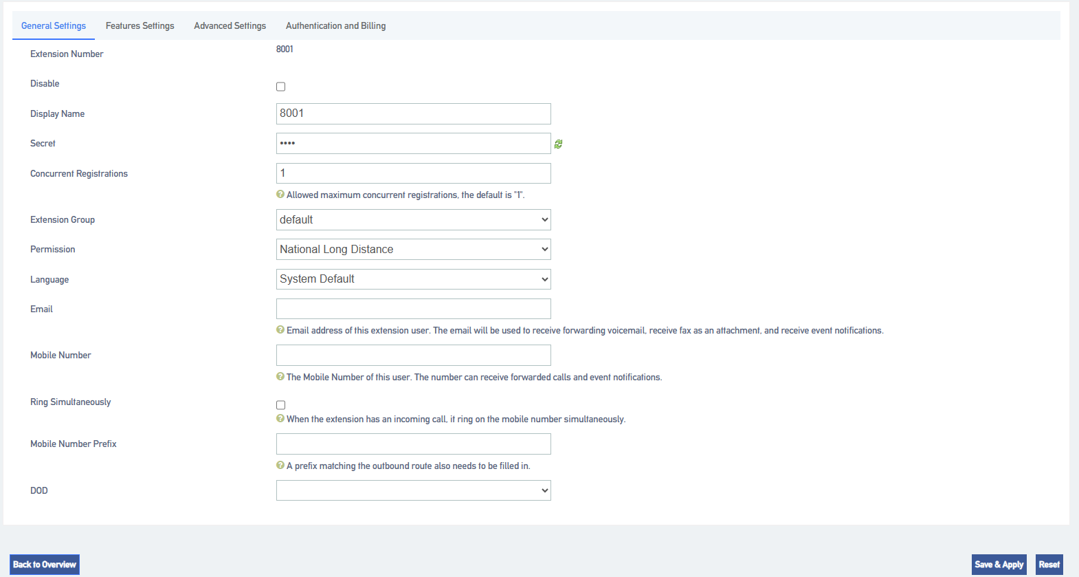
- On the [General Settings] screen, fill in the registration information of the SIP extension.
[Extension Number]: Set the extension number for incoming and outgoing phone calls.
[Display Name]: The name of the phone that the other party sees when the user dials.
[Maximum number of registrations]: IPPBX, supports multiple user terminals to be registered to the same extension number. Fill in 0 means that the number of user registrations is unlimited, and fill in 4 means that up to 4 users are allowed to register to this extension.
[Password]: The password to be filled in when registering to this extension.
[Email]:Fill in the user’s e-mail address. This e-mail address can be used to receive voice messages. Other settings: default.
2.Click [Save & Apply]
Batch creation of extensions:
- Log in to the IPPBX web page.
- Go to “Extension” -> “SIP Extension” and click [Bulk Add].
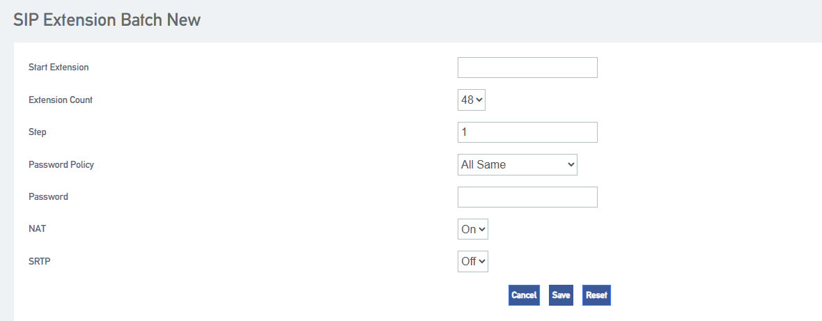
[Start extension]: Fill in the start extension number, the system will start with this number to create extension numbers in batch.
[Number of extensions]: The number of SIP extensions to be created in batch.
[Step]: Distance between each extension.
[Password Policy]: Set passwords for each extension.
- Same extension number: The password and extension number are the same for each extension.
- All the same: The password is the same for each extension.
- Random: The passwords for each extension are generated randomly.
[NAT]: When NAT is turned on, each extension can be registered remotely.
[SRTP]: When turned on, the extension’s voice will be encrypted during the call.
[Transfer Protocol]: Select the transfer protocol, the default is UDP.
4.Click on [Save & Apply]
5.2.2 Registering SIP extensions remotely
Users who work outside the office can also register to the company’s extension by downloading a SIP softphone on their cell phone and registering it remotely.
Show column:
The company has an IPPBX set up and the outside staff wants to register remotely to the company’s IPPBX via IP phones or SIP softphones.
-
- Company public IP address: 11.11.11.11.
- External port: 51000.
Preparation conditions:
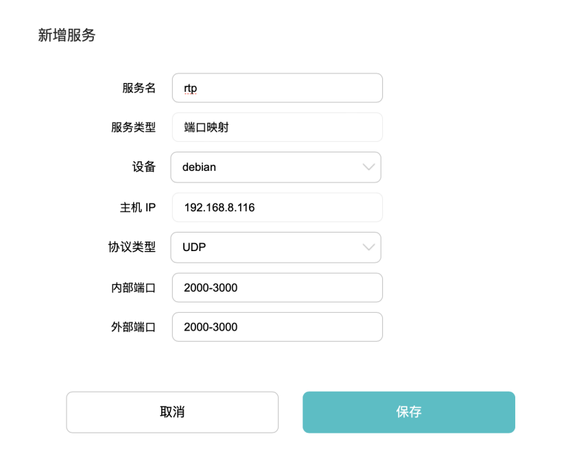
In the company, you need to set up the port mapping on the router connected to the IPPBX. If you do not set up the port mapping, the devices in the external network cannot connect and communicate with the IPPBX in the company. Tip: If the router supports SIP ALG function, please disable SIP ALG.
- SIP signaling port mapping
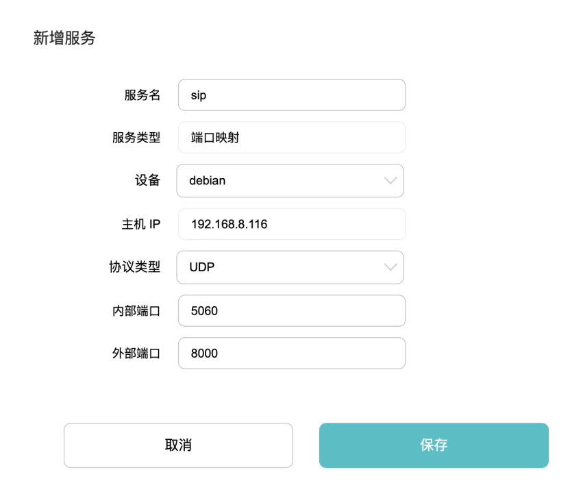
2.RTP port mapping
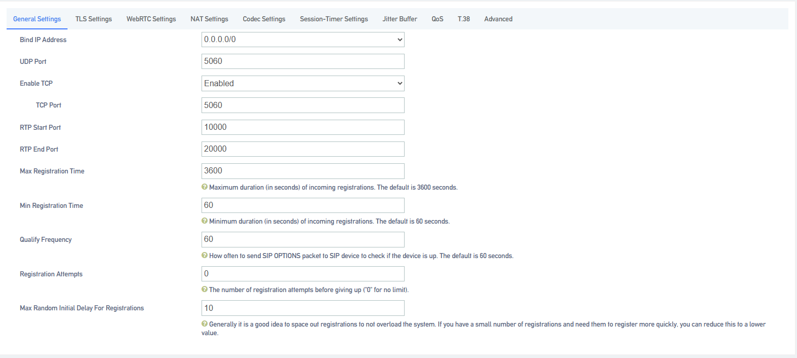
3.Configure NAT parameters for the IPPBX
Users can modify the port configuration of the corresponding router in Advanced Feature -> SIP -> General Settings.
4.NAT Configuration
Go to Advanced Features -> SIP -> NAT Settings to set NAT according to the IPPBX network environment.
[NAT Type]: In this example, the IPPBX has a static public IP address, select [Public IP Address].
Note: If IPPBX does not have [Static Public IP Address], users can select [Domain Name] for remote registration.
[Public IP Address]: Fill in the [Public IP Address] and [SIP External Port] of the IPPBX.
[Local Network Address]: Fill in the LAN segment where the local IPPBX is located.

Go to Extension->Sip Extension and click [Add or Edit].
On the SIP extension [Advanced Settings] page, check [NAT], [Remote Registration].
Enable NAT and remote registration for the extension.

Note: It is recommended to uncheck [Qualify] to disable heartbeat detection, otherwise remote extensions that have been registered are prone to drop out.
5.2.3 Modifying SIP extensions
- Modifying Individual Extension Information
- Log in to the IPPBX webpage and go to Extension -> SIP Extension.
- Under the Extension page, find the extension you need to set and click [Edit].
- Modify the extension to suit your application.
- Click [Save & Apply] when the modification is complete.
- Batch modification of extension information
- Log in to the IPPBX webpage and go to Extension -> SIP Extension.
- Under the Extension page, [check] the extension you want to modify and click [Edit].

- Modify the extension to suit your application.
- Click [Save & Apply] when the modification is complete.
5.2.4 Deleting SIP extensions
When there are some unneeded SIP extensions, users can choose to delete the unneeded SIP extensions.
- Delete a single SIP extension
- Log in to the IPPBX webpage and go to Extension -> SIP Extension.
- Under the Extension page, find the extension you need to delete and click [Delete].
- Batch delete SIP extensions
- Log in to the IPPBX webpage and go to Extension -> SIP Extension.
- Under the Extension page, [check] the extension you do not need and click [Delete].

3.Click [Save & Apply].
5.3 SIP extension configuration
This article will give users a detailed explanation, all the functions of the SIP extension settings.
5.3.1 SIP extension basic settings
Setting path: Click Extension -> SIP Extension, select a SIP extension, and click [Edit] to enter the [General Settings] page of the extension.
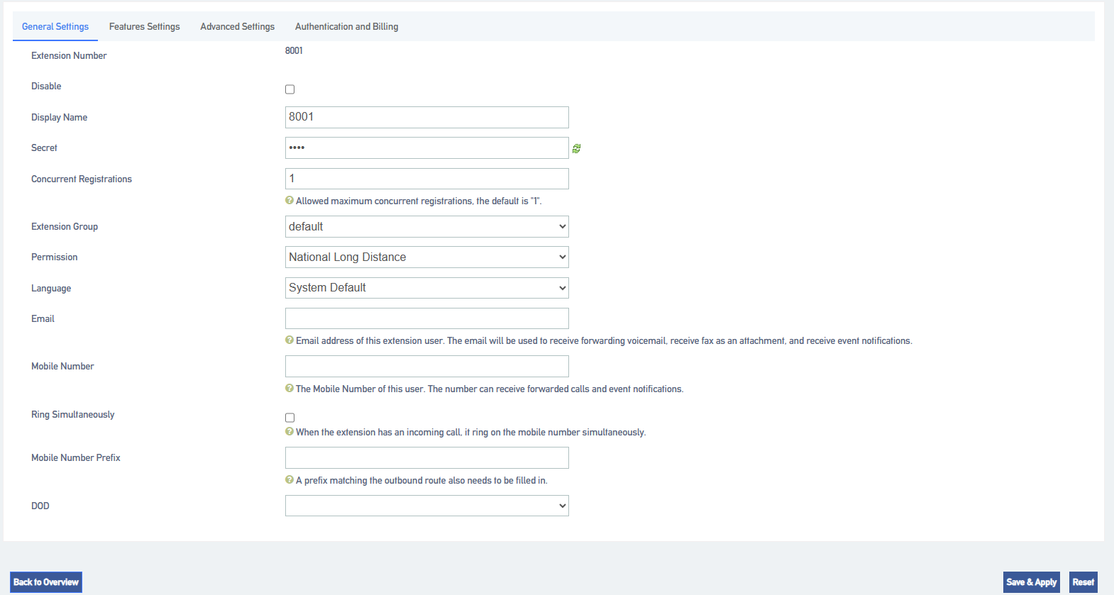
Setting parameters:
| set up | clarification |
| extension number | The extension number used to make and receive calls. |
| prohibit the use of sth. | When disabled, all functions of the SIP extension will not work properly and will not be able to be registered. |
| Display Name | Extension display name. |
| Register Password | Password required for SIP phone registration. |
| Maximum number of registrations | How many phone terminals are allowed to register to the same SIP extension. When an extension has an incoming call, all terminals ring at the same time. |
| subassemblies | Select an extension group, e.g., for a technical support staff extension, select the Technical Support group. See Extension Group Functions for details. |
| multilingualism | The language category of the prompt tone played by the system. Supports Chinese voice and English voice. |
| scope of one’s jurisdiction | Permission setting when an extension makes a call, there will be permission restriction when the extension makes a call to an outside line, if the permission of the extension does not meet the permission of the outside line, it will not be able to make an outgoing call.
|
| Fill in the user’s e-mail address. | |
| DOD port | Bound external port, this extension can directly call out to the outside world through the bound external port without permission setting. |
5.3.2 SIP extension function settings
- voicemail
When users are on a call or have other important matters that make it impossible to answer the incoming call, they can enable the voice mailbox function. When it is turned on, when the caller can not be connected, the caller will hear a message tone, and after listening to it, he/she can leave a voice message. After the message is finished, users can press *2 to listen to the message according to the operation prompts. The configuration is as follows:
Setting Path: “Extension” -> “SIP Extension”, select a SIP extension, click [Edit], and then come to the [Features Settings] page of the SIP extension.
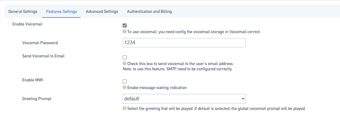
Setting parameters.
| set up | clarification | |
| Send a voice message to your mailbox | When enabled, you need to fill in the e-mail address. The message file received by the extension will be sent to the filled mailbox. | |
| Voicemail Password | The password that needs to be filled in when the user dials *2 or *02 to access the message menu after setting the password. | |
| Message Reminder | The message tone that will be heard when the other party calls and cannot be reached. | |
| default (setting) | System default tone. | |
| import speech | Imported into the IPPBX internal beeps. | |
| self-record | Currently record your own cues. | |
- Login/Logout
Click “Extension” -> “FXS” -> “Features Settings” and find the [Login/Logout] function.
- Login: When you select Login, you can dial the number normally.
- Logout: When you select Logout, you will not be able to make calls. However, the feature code will still work normally. (Default *105 login, *106 logout)
- distraction-free
Users who don’t want to be disturbed can automatically reject calls when they enable Do Not Disturb.
Setting Path: Click Extension -> FXS -> Features Settings, and find the Do Not Disturb function as follows.

Setting parameters:
| set up | clarification |
| cloture | Turn off Do Not Disturb mode. |
| normally open | It’s in do-not-disturb mode and no calls can come in. |
| appointed time | In no-disturb mode for a set period of time.
Example: The time period is 8:30-12:30.During this time period, no incoming calls will be received. |
| Applications:
*78, enable do not disturb. *79, cancel the do-not-disturb. Attention: After scrambling is turned on, any incoming calls, including ringing groups, IVRs, queues, etc., cannot be connected (except for broadcast groups). |
|
- secretarial extension
When an extension receives an incoming call, it transfers the call to the designated extension, which is the secretary extension.
Set the path:
Extension -> SIP Extension -> Features Settings, find [Secretary]. The content is as follows

Setting parameters:
| set up | clarification |
| secretarial extension | Select a number to bind to as a secretarial extension. |
| Insider to Secretary | The secretary extension can only be transferred when the device is called from inside the device. |
| Outside to Secretary | It can only be transferred to the secretary’s extension when an outside line is called in. |
- conditionality transfer
Conditional transfer is a very useful feature that can be done when the user is unable to answer an incoming call, or is in the middle of a call, or doesn’t have time to answer an incoming call.
Set the path:
Click Extension -> SIP Extension -> Features Settings and find Conditional Transfer as follows.

Setting parameters:
| unconditional transfer | All incoming calls are transferred to the specified destination. | |
| move quickly in an emergency | When in occupancy, incoming calls are transferred to the specified destination. | |
| No answer transfer | When a call is not answered, the call is transferred to the specified destination. | |
| Unconditional, busy, no-answer transferable destination | cloture | The unconditional transfer feature is off, by default. |
| leave a message | Transfer to voicemail. | |
| (telephone) extension | Transfer to the specified extension. | |
| repeat | Go to the designated outgoing number. | |
- monitor
When a user has listening privileges, he or she can listen to other users’ calls by pressing [Listening Feature Code] + [Extension Number to Listen] on the handset.
Set the path:
Go to Extension -> SIP Extension -> Features Settings and find the Secretary Listening function as follows.

Listening Settings:
In order to ensure the normal use of the listening function, you need to set up the listening function for both the listener and the listee at the same time.
- Set the [Listening Privileges] and [Listening Mode] of the listener.
- Log in to the IPPBX webpage, go to Extension -> SIP Extension, and click [Edit] next to the extension.
- On the extension edit screen, click the [Features Settings] screen.Select a listening mode from the [Monitor Mode] drop-down menu.
- Click on [Save & Apply]
Sets which extensions can be listened to:
- Log in to the IPPBX webpage, go to Extension -> SIP Extension, and click Modify next to Extension.
- On the extension edit screen, click the [Function Settings] screen.
- In the [Listening Settings] field, check [Allow to be listened to].
- Click on [Save & Apply]
Setting parameters:
| set up | clarification | |
| Allow to be listened to | tick | Allow listening by other extensions while on a call. |
| don’t tick | During a call, it cannot be listened to by other extensions. | |
| listener mode | prohibit the use of sth. | Unable to listen to other extensions. |
| common (use) | Able to use 3 listening schemes: normal, secret, and forced insertion. | |
| ordinary listener (computing) | Normal listening mode, can only be used for listening, can not talk to any party in the call.
Method: *90 + the extension number to listen to. |
|
| eavesdrop | Secret listening allows you to both listen and talk to the listener, but the other party talking to the listener cannot hear the listener’s voice.
Method: *91 + the extension number to listen to. |
|
| Force insertion of a listener | All three parties can make mutual calls.
Method: *92 + the extension number to listen to. |
|
- a relay
When an extension call is unanswered, other extension users can answer the call on behalf of the extension user. The extension pickup function is disabled by default. The settings are as follows:
Set the path:
Click Extension->SIP Extension->Features Settings to find the substitute connection function as follows.

Surrogate connection parameters:
| set up | clarification | |
| Prohibition of substitution | tick | Can’t be subbed. |
| unchecked | When an extension is unavailable, another extension is allowed to answer the call on your behalf. | |
| a relay | impermissible | Cannot be answered on behalf of an extension that is in a no-answer state. |
| within a group | Only extensions in the same group can be connected, not extensions in different groups.
Usage: Dial *4 (substitute for an extension in the same group), *04 + the number to be substituted. |
|
| security situation | The ability to substitute all extensions within the device.
Usage: Dial *4 (substitute for an extension in the same group), *04 + the number to be substituted. |
|
Example of a substitute connection:
- Substitute pickup within the group:
Users can set up a surrogate group in IPPBX in advance, and set the extensions of related personnel to the same extension group. When there is an incoming call from the personnel in the same group, the other personnel can press [Same Group Pickup Feature Code*4] on the handset to pick up the incoming call on their behalf.
Dial [*4] on your phone to answer the call on your behalf when the phone of a colleague in the same group rings.
- Designated substitute pickup:
If a coworker is not in the same group as you, you can answer the call on behalf of your coworker by dialing the specified [Pickup Feature Code] + the coworker’s extension number.
When your coworker’s phone rings (coworker’s extension number is 1000), the user can dial *041000- substitute caller on the phone.
- Surrogate feature code modification:
The default feature code of surrogate is: *4, *04. Go to Advanced Functions -> Feature Code, click Query, search for surrogate, and click Edit when you find it.
- Time limit for a single call
Limit the call duration for an extension to call an outside number. Different call lengths can be set for extensions dialing different types of outside numbers.
Set the path:
Extension -> SIP Extension -> Features Settings, find Single Call Limit as follows.

Single call time limit setting:
| set up | clarification |
| municipal language | Set the length of a single call when using local call routing. |
| internal (a country) | Set the length of a single call when using the domestic route. |
| global | Set the length of a single call when using international routing. |
| Instructions for use:
The type of call limit is determined by the authority of the calling route and has nothing to do with extension authority. Example: the extension is limited to 10 seconds for local calls, 20 seconds for domestic calls, and 30 seconds for international calls.
|
|
- extension roaming
This function is required when using a specific extension to dial an outside number.
Set the path:
Click Extension -> SIP Extension -> Features Settings to find the extension roaming function as follows.

Setting parameters:
| set up | clarification | |
| roaming permission | start using | Allow extensions to dial roaming numbers. |
| prohibit the use of sth. | The roaming function is prohibited. | |
| extension code | This extension password is the [Roaming Login] password and the extension [Login/Logout] password. | |
| Password Calling Privileges | internal call | Allows calls to extensions within the device. |
| municipal language | Numbers that allow calls to be made to a municipal telephone number. | |
| internal (a country) | Calls to domestic numbers are allowed. | |
| global | Allows calls to international numbers. | |
| Usage:
Roaming Feature Code (*88) + extension number + extension code + number to be dialed. Example: *88*2025*1234*136xxxxxxx. NOTE: Roaming call privileges, are not affected by extension privileges. |
||
- caller ring-back tone (CRBT)
This function is required when using a specific extension to dial an outside number.
Set the path:
Click Extension -> SIP Extension ->Features Settings to find the extension roaming function as follows.

Setting parameters:
| set up | clarification | |
| roaming permission | start using | Allow extensions to dial roaming numbers. |
| prohibit the use of sth. | The roaming function is prohibited. | |
| extension code | This extension password is the [Roaming Login] password and the extension [Login/Logout] password. | |
| Password Calling Privileges | internal call | Allows calls to extensions within the device. |
| municipal language | Numbers that allow calls to be made to a municipal telephone number. | |
| internal (a country) | Calls to domestic numbers are allowed. | |
| global | Allows calls to international numbers. | |
| Usage:
Roaming Feature Code (*88) + extension number + extension code + number to be dialed. Example: *88*2025*1234*136xxxxxxx. NOTE: Roaming call privileges, are not affected by extension privileges. |
||
- Call Waiting
When enabled, the analog phone is in a call and can still receive new incoming calls. And after pressing the tapping fork, you can hang up the other party’s phone and talk to the new caller.
- put through (to telephone extension)
When the forwarding feature is enabled, users can forward the current call to other users.
Note: The current IPPBX supports 2 types of transfer: [Blind Transfer], [Ask Transfer].
The configuration of the transfer is used as follows:
Configure the path:
Click Extension -> SIP Extension -> Features Settings and find the transfer function as follows.

Transfer settings:
| set up | clarification | |||
| call forwarding | start using | Enabled by default. When enabled, an extension, when acting as a caller, can forward the current call to another extension, or to an external number. | ||
| prohibit the use of sth. | Call Forwarding is not available. | |||
| called transfer | start using | Enabled by default. When enabled, an extension, when acting as a called, can forward the current call to another extension, or to an external number. | ||
| prohibit the use of sth. | Called forwarding is not available. | |||
Usage: Press *03 for blind transfer during a call, press *3 for inquiry transfer.
Consult the third-party user first and obtain the third-party user’s consent before transferring the current call to the third-party user. |
||||
- Hotline function
After the handset has been off the hook for a certain period of time, the handset will automatically call the specified number.
Set the path:
Click Extension -> SIP Extension -> Features Settings and find the Hotline function as follows.

Setting parameters:
| set up | clarification |
| hotline (communications link) | The Hotline function is available when checked. |
| hotline number | Fill in the hotline number. |
| dial delay | Waiting time for outgoing hotline numbers after taking off the phone. |
Hotline example:
The manager of a company often calls to contact his assistant to deal with work matters. After setting up a hotline number, the manager can simply pick up the call handle and make a call to his assistant.
Go to Extensions -> SIP Extensions and find the manager’s extension (example: 2005).
Click Edit -> Features Settings, find the Hotline function and turn it on.
Fill in the [Hotline Number] field with the assistant’s extension number (Example: 2006).
In the [Dial Delay] field, set to 2 seconds.
- ringing time
Set the ringing duration of the extension.
5.4 Sub-groups
5.4.1 Creating subgroups
Split group can be a good way to divide members from different departments and organizations into different groups. In the subsequent call management, you can directly manage the members of the whole group, without the need to manage the configuration of one member at a time.
The steps for creating a subgroup are as follows:
- Go to “Extension” -> “Department” and click [Add].
- Fill in the [Name] column to identify the name of the subgroup.

- Extension group call authority setting
- Allow Outside Call-In: When turned on, outside calls can be made to members of this extension group.
- Allow Extension Mutual Dialing in Group: when turned on, allows extension members in a group to dial numbers from each other.
2.In the [Optional] box, select a member extension to add to the Selected box.
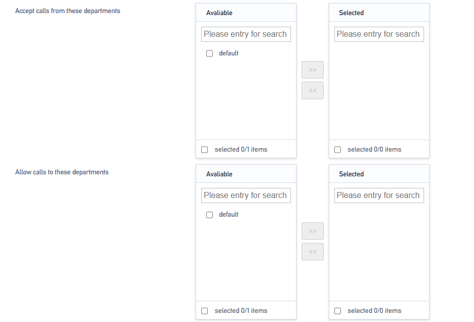
- Allow calling in to other user groups:
Once added, you can dial to other user group members.
- Allow other user groups to call in:
Once added, allow members of other user groups to type in.
Application Examples:
A member of group A wants to call a member of group B. The configuration is as follows:
- Group A. In [Allow calling in other user groups], add Group B to the checked box.
- Group B. In [Allow other user groups to call in], add Group A to the checked box.
- Click [Save & Apply].
Similarly, in order for a member of group B to call a member of group A, the configuration steps above need to be followed.
- Group B. In [Allow calling in other user groups], add Group A to the checked box.
- Group A. In [Allow other user groups to call in], add Group B to the checked box.
- Click [Save & Apply].
5.4.2 Editing subgroups
If you need to perform the function [Edit] for the group of extensions, the modification procedure is as follows:
- Go to Extension -> Department, search and find the extension group you want to edit, and click [Edit].
- Edit the subgroups as needed.
- Click [Save & Apply].
5.4.3 Deleting subgroups
If you need to delete the subgroup. The deletion procedure is as follows:
1. Go to Extension -> Department, search and find the extension group you want to edit, and click [Delete].
2. Click [OK] to delete the subgroup.
5.5 Voice mail
5.5.1 Turning voicemail on/off
Enable/disable voicemail
- Go to Extension -> FXS/Sip Extension, search and find the extension you want to set, and click [Edit].
- On the Extension Edit page, click Features Settings.
- Turn on voicemail.
- Check the box: to enable the voicemail feature for the extension.
- Turn off voicemail.
- Unchecked: The extension will not be able to use the voice message function.
- Click [Save & Apply].
Voicemail password change
After turning on the voice mailbox, if no password is set, users can dial *2 (the default message feature code) directly at the extension to listen to the message. For security reasons, extension users should set a mailbox password.
- Go to “Extension” -> “FXS/SIP Extension”, through the search user can quickly find the extension to be set, click [Edit].
- On the extension editing screen, click [Features Settings].
- Check [Enable Voicemail] to enable the voicemail function of the extension.
- In the [Voicemail Password] field, fill in the new password.
- Click [Save & Apply].
Setting up voicemail to mailbox
- Configuring SMTP
If you want to enable sending voicemail to your own mail, then you must configure SMTP. the configuration is as follows:
Configure the path:
Go to Advanced Feature -> SMTP Settings and come to the SMTP configuration page.

Setting parameters:
| set up | clarification |
| Enable Mailbox | Enable the mailbox. |
| SMTP server settings | Fill in the SMTP service address, either IP address or domain name.
Common SMTP server address format: SMTP.XXXX.com Example. QQ’s server address: SMTP.qq.com Netease’s service address: SMTP.126.com / SMTP.163.com |
| SMTP port number | Fill in the port number of the SMTP mailbox server:
The filling of the port number depends on the rules of the mailbox you are using. Take QQ mailbox for example: If the tls/ssl connection is not enabled, transfer port 25. If the tls/ssl connection is enabled, the transfer port is 465. |
| Connecting using TLS | Enable TLS transport connections. |
| Using the STARTTLS protocol | It can be turned on if the mailbox server supports it, and needs to be turned off if it doesn’t. |
| SMTP server authentication method | Select the login authentication method:
Login Plain Off |
| user ID | The account used to log in to your mailbox. |
| cryptographic | Fill in the authorization code for the mailbox. |
| SMTP Test | Verify that the mailbox is available. |
2.SMTP Application Examples
To use it, you need to enable the SMTP service of the mailbox.

After the configuration is complete, first click [SAVE & APPLY], and then click [SMTP TEST]. If everything before the configuration is no problem, finally received exitcode = EX_OK, that the configuration is successful.
3.Enable voice message to mailbox
By default, IPPBX disables the voice message to mailbox function. If users need to enable this function, they need to enable it manually, and the configuration steps are as follows:
Note: Ensure that the extension has been bound to an e-mail address and the system mailbox setting of IPPBX is correct, otherwise [Voice Message to E-mail] will not work properly.
- Go to Extension -> FXS/Sip Extension, search and find the extension you want to set, and click [Edit].
- On the extension editing screen, click [Features Settings Tab].
- Check [Enable Voicemail] to enable the voicemail function of the extension.
- Check the box [Send voice message to mailbox].
- Click [Save & Apply].
- Settings Voicemail to Mailbox Email Templates
- Go to Advanced Feature -> Voicemail.
- Edit [Subject] and [Sign].
- Click [Save & Apply].
5.5.2 Listening to voice messages
Check your messages through the extension:
- Dialing feature code *2:
Users can press *2 to view voice messages on their own handset.
- Dial feature code *02:
Users can press *02 on another extension user’s phone to access the Voicemail Main Menu, enter their extension number and Voicemail PIN, and view incoming voicemail messages.
View voice messages via e-mail:
Users can listen to or view voice messages through the mailboxes bound to their extensions. The prerequisite is that the user has enabled the function of leaving messages to the mailbox….
Produce a message reminder tone:
- Go to Advanced Feature -> Voice Prompts -> Custom Prompt, and click to import the prompt tone you have made.
- Note: Cue upload format, only supports 8000hz, mono, 16 bit width.
- After uploading the cue, go to Advanced Feature -> Voice Prompts -> Hold On Music and click [Add].
- In the Prompts optional list, add to the Selected list.
- Fill in the name.
- Click [Save & Apply].
Modify the message alert tone:
- Go to Extension -> FXS/Sip Extension, search and find the extension you want to set, and click [Edit].
- On the extension editing screen, click [Features Settings Tab].
- Check [Enable Voicemail] to enable the voicemail function of the extension.
- In the Reminder Options drop-down menu, check the previously created message reminder.
- Click [Save & Apply].
Record a message tone on the extension:
- Dial *02 on the extension.
- According to the voice message menu, press the corresponding function button to record the message prompt tone.
5.5.3 Voice mail settings
Users can go to Advanced Feature -> Voicemail and modify its functions according to their own usage needs.
| Message Options | |
| Maximum number of voicemails per folder | Set the maximum number of voice messages that can be saved in each folder of the extension. |
| Maximum message time | Set the maximum message time for each voice message. |
| Minimum message time | Set the minimum message time for each voice message. |
| Delete Voice Messages | When enabled, the system automatically deletes voice messages that have been sent to the mailbox, and is not enabled by default. |
| storage location | Stores the message in the specified location. |
5.5.4 Voice mail function menu
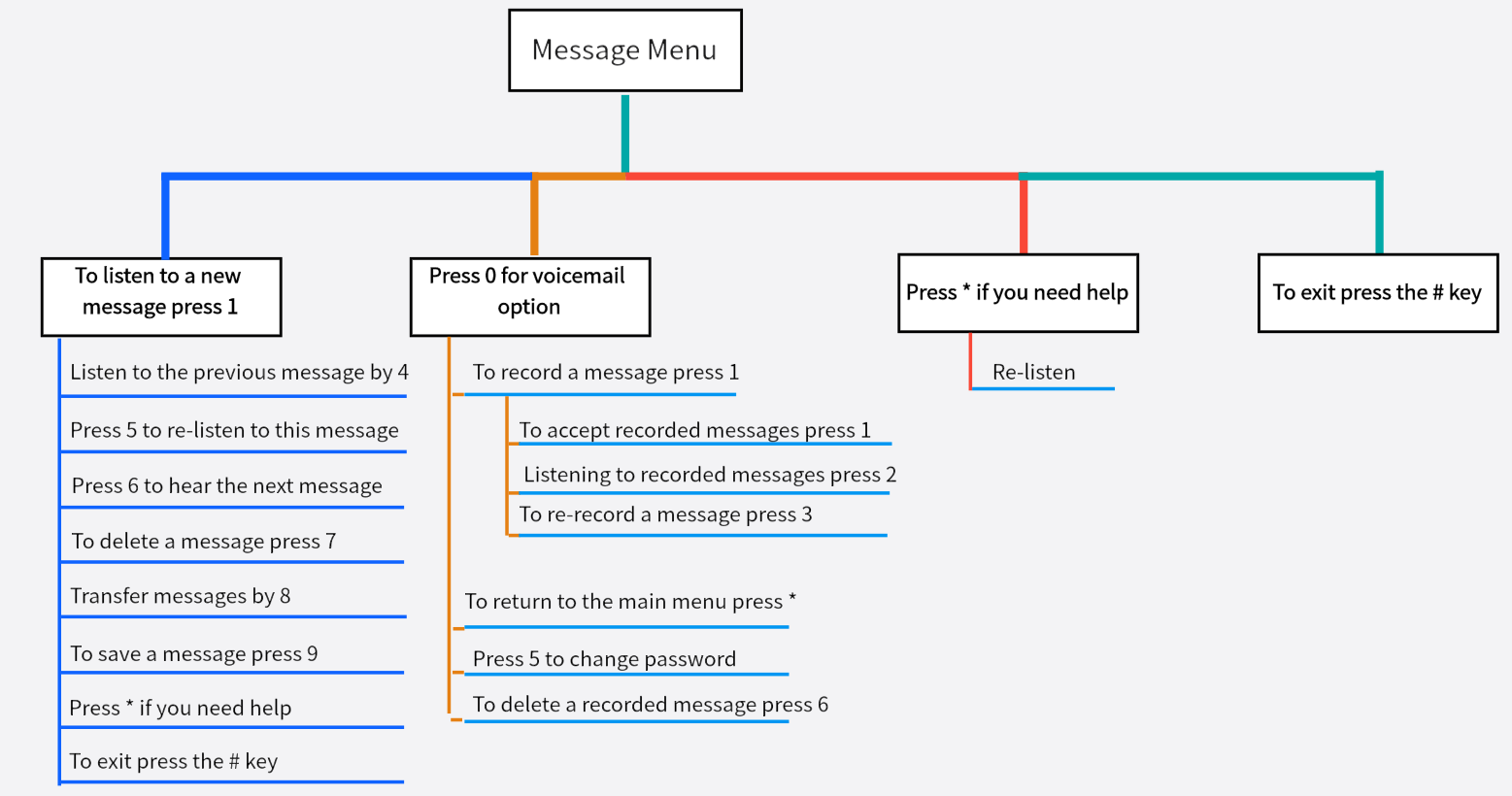
The menu is shown below. Dial *2 and enter your voicemail password to access the main menu of voicemail features.
6 Trunk
Users need to configure at least one trunk on the IPPBX to make and receive outgoing numbers.
6.1 Analog trunk
6.1.1 Analog Trunking Configuration
Configuration Path: “Trunk” -> “FXO” -> “General Settings”, edit the corresponding trunk in the [General Settings] page.
Configuration parameters:
| set up | clarification |
| DiD | Set the called number. |
| Incoming call detection mode |
|
| telephone dialing system | This option specifies the Caller ID signal type. The following types are included:
|
| Caller ID Sensitivity | |
| Type of hang-up detection | Select the type of hangup detection:
|
| Response detection type | Answer detection helps the system to accurately calculate the duration of your call.
Once you make an outbound call using an analog trunk, the IPPBX starts counting time whether the call is answered or not.
If the analog trunk supports antipode signaling, then you can choose antipode detection. When the called person answers, the provider sends an antipode signal and then the system starts to calculate the talk time. |
Advanced Configuration Path: “Trunk” -> “FXO” -> “Advanced Settings”, edit the corresponding trunk in the [Advanced Settings] page.
Configuration parameters:
| set up | clarification |
| Input Gain | Sets the volume of the receive channel of the analog FXO port. |
| Output Gain | Sets the volume of the analog FXO port transmit channel. |
| Turn off echo cancellation | Turning it on will turn off echo canceling. |
| Delayed dialing (milliseconds) | The time between the FXO going off-hook and delivering the DTMF called number. If the value is set too small, it may cause the opposite-end equipment to miss detecting the number, and too large will prolong the connection time. It is usually sufficient to keep the default value, which is 1500. |
6.2 SIP Trunking
6.2.1 SIP Trunking Overview
SIP trunks, like traditional analog trunks, require a phone number to be provided by the carrier and routed to the IPPBX phone system. However, compared to traditional analog trunks, SIP trunks are cheaper and are easier to deploy and implement as they enable phone line calls over IP.
- SIP trunk type
The IPPBX supports the following types of SIP trunks:
- Registered Trunking: registration type of trunking. The user registers to the operator using the user name and password provided by the operator.
- Point-to-Point Trunking: IP-based trunking. It is mainly used for networking interconnection between IPPBXs, and can also use domain name or public IP address to register to the relay operator.
- Account Trunking: Users can create an account in IPPBX and other gateways connect to this IPPBX by registering this account.
6.2.2 SIP Trunk Creation Methods
The IPPBX supports two ways to create SIP trunks:
-
- Import Creating SIP Trunks
Users can import to the IPPBX after filling in the configuration information on the relay imported template.
2.Creating SIP Trunks Routinely
- Creating a Registered Relay
- Creating point-to-point relays
- Create an account relay
Create a SIP registered trunk:
Suppose the user has purchased a SIP trunk from the carrier, and the trunk information is shown in the following table. This article describes how to register a SIP trunk at the IPPBX based on this SIP trunk information.
| Service provider’s domain name | Mobile.ims |
| pact | SIP |
| SIP port | 5060 |
| transportation protocol | UDP |
| user ID | test |
| Certified Name | test |
| cryptographic | Test123 |
- Go to Trunk -> SIP Trunk.
- Fill in the relay name in the relay [Name] field.
- Select Enable in the [Relay Status] field.
- In the [Relay Type] drop-down list, select [Registered Relay].
- Complete the following configuration based on the information provided by your SIP trunk service provider:
| registered relay | transportation protocol | UDP |
| SIP address | The domain name or IP address of the service provider. Example: (qsc.wellcome.com). | |
| SIP port | Used for ports when other devices are registered. Example: 5060. | |
| domain | The server domain name of the SIP trunk operator. If there is no domain name, please fill in the IP address. | |
| user ID | SIP trunk account for registering a SIP provider. Example: 123456. | |
| Certified Name | Used for SIP authentication. In general, please fill in [User Name] in this field. Example: 123456. | |
| cryptographic | Password for the SIP trunk account to register with the SIP provider. Example: asdwrxfwqxfq. | |
| From header fields | Customize the UserName portion of the From header field in Invite messages. | |
| proxy server | The default is none. | |
| certification domain | The server authentication domain of the operator. If not provided, it is not required. |
- Users can modify other relay configurations according to their needs.
- Click [Save & Apply].
Click into Trunk -> SIP Trunk to check the status of the trunk. If the trunk is successfully registered, the registration status will show that it is in effect.
Create a SIP point-to-point trunk:
Assuming that the user has bought a SIP trunk from the carrier, the trunk information is as follows. The following schematic columns will help the user to further understand the configuration of point-to-point trunks.
| Service provider’s domain name | peer.sip.com |
| pact | SIP |
| SIP port | 5060 |
| transportation protocol | UDP |
- Go to Trunk -> SIP Trunk.
- Fill in the relay name in the relay [Name] field.
- Select Enable in [Relay Status].
- In the [Relay Type] drop-down list, select Point-to-Point Relay.
- Complete the following configuration based on the information provided by your SIP service provider:
- In the [Domain Name/IP Address] field, fill in the IP address or domain name provided by the relay service provider (e.g., peer.sip.com).
- In the [Primary Domain Server] field, fill in the domain address provided by the relay service provider (e.g., peer.sip.com).
- Modify other SIP trunk configurations as needed.
- Click [Save & Apply].
Click to go to Status -> PBX Monitor to check the status of the trunk. If the trunk is successfully registered, the registration status will show that it is in effect.
Create a SIP account trunk:
Users can create a SIP account trunk in IPPBX for interfacing with IPPBX and other devices. The steps are as follows.
- Go to Trunk -> SIP Trunk.
- Fill in the relay name in the Relay [Name] field.
- Select Enable in [Relay Status].
- In the [Relay Type] drop-down list, select Account Relay.
- Modify other SIP trunk configurations as needed.
- Click [Save & Apply].
- When other IPPBX registers to this IPPBX, you can click into Trunk -> SIP Trunk to check the status of the trunk. If the trunk is successfully registered, the registration status will show that it is in effect.
6.2.3 Management relay
Importing a registered relay:
Users can batch create SIP trunks by importing a file in UTF-8.csv format. For specific import configuration, users can check [Import Parameters Instruction Manual] for SIP trunk import. The following is how to import SIP trunks to the device.
- Go to Trunk -> SIP Trunk
- Click Import, and in the pop-up dialog box, check the relay file you need to import.
- Once selected, click Open.
- Wait for the import to complete.
Edit the SIP trunk:
- Go to Trunk -> SIP Trunk.
- Search and find the SIP trunk you want to edit and click [Edit].
- Modify the relevant configuration according to your needs.
- Click [Save & Apply].
Delete the SIP trunk:
- Go to Trunk -> SIP Trunk.
- Search and find the SIP trunk you want to edit and click [Delete].
- On the pop-up screen, click [Yes] to confirm the deletion.
- Click [Save & Apply].
6.2.4 SIP Trunking Configuration
When configuring trunks, users may need to modify some settings. This article describes the configuration of SIP trunks in detail.
Basic settings:
Setting path: “Trunk” -> “SIP Trunk”, in the overview page, configure the corresponding trunk.
Relay name: (not modifiable) (set at new creation).
Trunking Status: Enable/Disable. You can choose to enable or disable trunking.
DID number: When the outside line calls in, it will directly transfer to the specified extension number with higher priority than the inbound route, when the DID number is not set or the DID number is invalid, it will be processed according to the inbound route.
Other settings:
| typology | set up | clarification |
| registered relay | transportation protocol | UDP/TCP/TLS. |
| SIP address | The domain name or IP address of the service provider. | |
| SIP port | port of the service provider. | |
| domain | The server domain name of the relay operator. If no domain name is available, please fill in the IP address. | |
| user ID | Trunking account for registering SIP providers. | |
| Certified Name | Used for SIP authentication. Usually the same as the username. | |
| cryptographic | The password for the trunk account, which is used to register with the SIP provider. | |
| From header fields | Customize the UserName portion of the From header field in Invite messages. | |
| proxy server | The default is none. | |
| certification domain | The server authentication domain of the operator. If not provided, it is not required. | |
| Account Relay | transportation protocol | UDP/TCP/TLS. |
| user ID | User name to be filled in for other devices to register to this IPPBX. | |
| cryptographic | The registration password to be filled in for other devices registered to this IPPBX. | |
| From header fields | Customize the UserName portion of the From header field in Invite messages. | |
| proxy server | The default is none. | |
| point-to-point relay | transportation protocol | UDP/TCP/TLS. |
| SIP address | The domain name or IP address of the service provider. | |
| SIP port | 5060. | |
| domain | The server domain name of the relay operator. If no domain name is available, please fill in the IP address. | |
| Certified Name | For SIP authentication. Generally, please fill in the “User Name” in this field, and fill in the trunk authentication name of the trunk service provider. | |
| cryptographic | Password for the SIP trunk account to register with the SIP provider. | |
| From header fields | All outgoing calls from this trunk will apply this name to the Username portion of the From header field of the SIP INVITE signaling. | |
| proxy server | The default is none. |
Advanced Settings:
Generally, users do not need to change the advanced settings of SIP trunking. Before setting up SIP trunks, users need to familiarize themselves with the SIP protocol, incorrect configuration may result in connection failure or no call.
Setting Path: “Trunk” -> “SIP Trunk”, edit the corresponding relay in the [Advanced Settings] page.
SIP trunk settings:
| set up | clarification | |
| Qualify | Check this item to have the IPPBX periodically send SIP OPTIONS packets to the phone to verify that the phone is online. | |
| NAT | Once turned on, you can register to other IPPBXs through the extranet. | |
| DTMF | RFC2833 | The DTMF signal is separated from the voice path and transmitted to the platform via RTP packets in RFC2833 format. |
| inband | DTMF is transmitted via RTP with voice packets. | |
| info | Separate the DTMF signal from the voice path and transmit it to the platform as a SIP signaling INFO message. | |
| SRTP | Check the box to enable SRTP encryption mode for voice calls. | |
| Support for T.38 | Enable the fax function. When enabled, it will consume some performance. It is not recommended to turn on this item when you have a large number of concurrent calls. | |
| Maximum number of channels | The number of concurrent calls allowed. | |
| irregular heartbeat | The interval in seconds at which SIP OPTIONS are sent at regular intervals. | |
| registration interval | How many seconds to re-initiate a registration to avoid broken links. | |
| User Phone | Sets whether to add the parameter user=phone to the request line in the SIP header field of the INVITE packet. The prerequisite for this configuration is that you should be familiar with the SIP protocol, and incorrect configuration may cause problems with the call. | |
| 100rel | Whether the 100rel protocol is supported. | |
| Custom Fields | Define custom fields based on IPPBX requirements. | |
Inbound parameter settings:
| set up | clarification |
| Calling Number Acquisition | Set which field in this trunk to get the calling number from
|
| DID Get | Set which field in this trunk to get the DID number from
|
Callout parameter settings:
| set up | clarification |
| Remote-Party -ID | Sets whether Remote-Party -ID is carried in the SIP header field of the INVITE packet; the default is not carried.
|
| P-Asserted-Identity | Sets whether P-Asserted -Identity is carried in the SIP header field of the INVITE packet; the default is not.
|
| P-Preferred-Identity | Sets whether P-referred Identity is carried in the SIP header field of the INVITE packet; the default is not carried.
|
7 Outbound Routers
7.1.1 Introduction to call routing
Outbound routing is used to tell the IPPBX which extensions can use this outbound routing and which trunk to use for outgoing calls.
Outbound Routing Application Principles
When an extension user dials a number, the IPPBX performs the following actions strictly:
- Check the number dialed by the extension user.
- Compare whether the outgoing number matches the outgoing pattern of the first outgoing route.
- If it matches, the IPPBX will be called out by the associated trunk through this outbound route.
- If there is no match, the IPPBX compares the match between the outgoing number and the outgoing pattern of the second outgoing route.
7.1.2 Number Matching Rules
| outbound mode | clarification |
| X | Represents any number from 0 to 9. |
| Z | Represents any number from 1 to 9. |
| N | Represents any number from 2 to 9. |
| [123459] | Represents any number in parentheses, e.g., in this example, the numbers: 1,2,3,4,5,6,7,8,9. |
| Wildcard “.” | Represents any numeric number with a length greater than 0. For example, “_9011.” represents that any number beginning with 9011 (excluding 9011) will be added to the list. |
| Wildcard “!” | This wildcard represents the end of number matching and can be used optionally when determining the length of the number. For example, if you only need to match four-digit numbers, you can enter “_XXXX!” to indicate that all four-digit numbers will be added to the list. |
7.1.3 Creating Outbound Routes
In order to dial an outside number through IPBBX, users need to create a call route.IPPBX has 3 built-in call routes by default, and the rules for outgoing calls are as follows: to dial local calls, add 9; to dial long distance, add 90 to the prefix of the number; and to dial international calls, add 900.To dial outside numbers, users of extensions must follow the above dialing rules. Of course, you can delete the default call routes and create new call routes according to your needs.
- Go to Call Control -> Outbound Routers and click [Add].
- Configure the outgoing route on the [Outgoing Routers] edit screen.
[Name]: Fill in the name of the call-out route.
[Description]: Remarks call out routing.
[Authority]:Only if the authority of the extension is greater than the authority of the outgoing route, you can make an external call.
[Priority]: When multiple outgoing routes share the same trunk for outgoing, the higher priority is used first.
[Time Rule]: Optional. Set the time period in which the user can use the outgoing route. The default is empty, users can use the outgoing route to call out at any time.
[Source Type]: Select which extensions can use this call routing.
- Any: All types of extensions can pass through this circuit and make outgoing calls.
- Analog Extension: Only analog extensions can make outbound calls through this outbound route.
- SIP extension: only sip extensions can make outbound calls through this outbound route.
[Calling Number Matching]: Only extensions that satisfy the matching rules can make outbound calls.
[Called Number Matching]: The number dialed by the extension user can only be called out externally if it meets the matching rules.
[Called Number Replacement and Calling Number Replacement]: (optional, off by default). When [Calling/Called Number Replacement] is turned on, you can replace the calling number and the called number. For specific configuration, see Number Change The following is the detailed configuration of the number change.
3.Click [Save & Apply].
Note: After setting up the outbound routing, you need to check and adjust the priority of the outbound routing to ensure that the IPPBX is able to match the correct outbound routing.
7.1.4 Adjusting the Priority of Outbound Routes
When the outgoing number dialed by the user meets the matching rules of multiple outgoing routes, the user can adjust the priority of each outgoing route, and the IPPBX will select the outgoing route with the highest priority for outgoing calls.
Note: The priority of the outgoing route is critical, especially when the user dials a number that matches more than one dialing pattern. For example, if the number 1234567 matches both the dialing patterns “ZXXXXXXXX” and “X.”, the IPPBX will use the outgoing route with higher priority to call out through the corresponding trunk.
Example: A user dials the number 901234567, and both of the following outbound routes match the number:
- Long distance outbound routing: outbound rule of 90, using trunk A.
- City call routing: outgoing rule is 9X. using trunk B.
If you want the IPPBX to use Trunk A to call out the phone number 1234567, you need to adjust the outgoing route of “Long Distance” to the front; otherwise, if the IPPBX matches the outgoing route of “Local” in priority, it will call out using Trunk Otherwise, if the IPPBX matches the outgoing route of “local call” in priority, trunk will be used. The configuration steps are as follows.
- Go to Call Control -> Outbound Routers .
- Select the call routes that need to be modified in priority and click [Edit].
- In the [Priority] option field, adjust the priority, the higher the number the higher the priority.
- Click [Save & Apply].
7.1.5 Editing call routes
- Go to Call Control -> Outbound Routers.
- Click [Edit] next to the inbound route.
- Change the configuration of [Inbound Routers].
- Click [Save & Apply].
7.1.6 Deleting an outgoing route
- Go to Call Control -> Outbound Routers.
- Click the [Delete] button next to the callout routing.
- In the pop-up window, click [Yes].
Note: After deleting the outgoing route, extension users cannot call out through this outgoing route.
7.2 Time conditions
Users can apply time groups to inbound routing and outbound routing, and the IPPBX will handle incoming calls and control users to dial outgoing numbers according to the time groups.
7.2.1 The role of temporal conditions
- Application of time conditions to inbound routing:
Users can add time conditions to the inbound routes and set different destinations according to different time conditions. When an external user calls, IPPBX will select an inbound route that meets the time condition according to the user’s incoming time and guide the incoming call to the appropriate destination.
- Application of temporal conditioning to outbound routing:
After a time condition is set for the outgoing route, an extension user of the IPPBX can only dial an outside line through this route within the time condition.
7.2.2 Setting time conditions
This article describes how to set working hours, breaks, and holidays on IPPBX.
Set the working time:
Users can create a time condition based on their working hours and later apply that time condition to the inbound routing to direct incoming calls during office hours to the appropriate destination.
- Go to Configuration “Call Control” -> “Time Profiles” and click [Add].
- The following settings are available on the Time rules screen
[Name]: Fill in the name of the time condition. Example: working hours.
[Description]: Describe its use.
[Time interval]: Set the time according to your working time. Example: 8:00-12:00 is the morning working time, 13:20-17:50 is the off-duty time.
[Period]: Select a weekday. Example: Every Monday through Friday is a working day
[Date range]: Set the month and day if necessary. If set to null, it will indicate that the whole year applies.
3.Click [Save & Apply].

Set up breaks:
Users can create a time condition based on their breaks and later apply that time condition to the inbound routing, after which all incoming calls during breaks will be directed to the appropriate destination.
Example: The company wants to take a break at noon when the customer’s incoming calls are directed to the front desk, so that the break will not disturb the company’s personnel, but also to ensure that customer service calls are not missed. The above scenario can be configured in this way:
- Go to Call Control -> Time Profiles and click [Add].
- The following settings are available on the Time rules screen
[Name]: Fill in the name of the time condition, e.g.: rest time.
[Description]: Describe its use.
[Time interval]: Set up according to the company’s lunch break. Example: 12:00-13:20 at noon.
[Period]: Select a weekday. Example: Monday through Friday are working hours.
[Date range]: If necessary, you can set the month and day. If set to null, it will indicate that it applies throughout the year.
3.Click [Save & Apply].

Set holidays:
Users can set multiple holidays and apply them on the inbound routing, after which all incoming calls during holiday time will be directed to the set destination. For example: IVR. when a customer calls into the IPPBX during holiday time, the IPPBX will inform the customer that the enterprise is on vacation via IVR voice.
- Go to Call Control -> Time Profiles and click [Add].
- The following settings are available on the Time rules screen
[Name]: Fill in the name of the time condition, e.g., weekend vacation.
[Description]: Describe its use.
[Time interval]: Leave blank.
[Period]:Select a vacation day. Example: Saturday, Sunday.
[Date range]: If necessary, you can set the month and day. If set to null, it will indicate that it applies throughout the year.
3.Click [Save & Apply].


7.2.3 Application of time conditions
After creating a time condition, users can apply the time condition to inbound routes and outbound routes. Users can also edit and delete time conditions as needed.
Apply time conditions to inbound routes:
Users can apply time conditions in inbound routing to direct incoming calls to different destinations based on office hours and schedules.
- Go to Configuration “Call Control” -> “Inbound Routers” and click [Edit].
- In the Inbound Routing [Time Profile] field, select a time rule.
- In the [Destination] column, select a destination, and when the IPPBX receives an incoming call, if the time of the incoming call, meets the time period corresponding to the time condition, the IPPBX will send the incoming call to the specified destination.
- Click [Save & Apply].
Applying temporal conditions in outbound routing:
The user can apply a time condition to the outbound route. An extension user can make outgoing calls through this route only during the time period specified by this time condition.
- Go to Configuration “Call Control” -> “Inbound Routers” and click [Edit].
- In the [Time Profile] field, select a time rule.
- In the [Destination] column, select a destination through which the extension user can make outgoing calls through this route only during the time period specified by this time condition.
- Click [Save & Apply].
7.3 Black/white lists
Blacklist is used to filter phone numbers. If a phone number is added to the black list, the system blocks inbound and outbound calls to that number. A whitelist removes the system’s blocking of this phone number. Whitelisting has a higher priority than blacklisting.
7.3.1 Black/white list settings
Users can set [Black/White List] for all extensions, or set [Black/White List] for specified extensions. The settings are as follows:
- Go to Call Control -> Black/White List and [Add or Edit] the black list or white list.
- There are three types of blacklist and whitelist restrictions:
[Calling in]:
- Blacklists in which added member numbers cannot call into the IPPBX or specified extensions;
- In the whitelist, added member numbers can call into the IPPBX or specified extensions, ignoring blacklist restrictions.
[Exhales]:
- In the blacklist, the specified extension user cannot call the member numbers in the blacklist;
- In the whitelist, the specified extension user can call the member numbers in the whitelist, ignoring the blacklist restrictions.
[Exhale and exhale]:
- In the blacklist, the specified extension users cannot call the member numbers in the blacklist, and the blacklist member numbers cannot call into the IPPBX or the specified extensions.
- In the whitelist, the added member numbers can call into the IPPBX or specified extensions, and the extension users can also call the member numbers in the whitelist, ignoring the blacklist restrictions.
7.3.2 Rules for adding black/white list members
| Matching rules | clarification |
| X | Represents any number from 0 to 9. |
| Z | Represents any number from 1 to 9. |
| N | Represents any number from 2 to 9. |
| [123459] | Represents any number in parentheses, e.g., in this example, the numbers: 1,2,3,4,5,6,7,8,9. |
| Wildcard “.” | Represents any numeric number with a length greater than 0. For example, “_9011.” represents that any number beginning with 9011 (excluding 9011) will be added to the list. |
| Wildcard “!” | This wildcard represents the end of number matching and can be used optionally when determining the length of the number. For example, if you only need to match four-digit numbers, you can enter “_XXXX!” to indicate that all four-digit numbers will be added to the list. |
7.3.3 Blacklist Example
Below is an example of a blacklist setup.
- Blocking Inbound Calls from External Numbers
For example: to prohibit the numbers 10086 and 1008611 from calling IPPBX. add a blacklist with the following settings:

- Prohibit Number Incoming and Outgoing Calls: Prohibits extension users from calling specified numbers, and these specified numbers cannot call into the IPPBX.
For example, calls to the numbers 10086 and 1008611 are prohibited and these numbers cannot call into the IPPBX.

- Prohibit numbers from calling in to the specified extension.
When an extension user encounters a nuisance call, the nuisance call can be blacklisted so that it cannot call into the nuisance extension.

- Prohibit an extension from calling a number that matches the rule in question.
For example, all members are prohibited from dialing four-digit numbers beginning with 5.

7.3.4 Whitelisting
Whitelists have a higher priority than blacklists, so whitelists generally work by filtering trusted numbers from the banned list and allowing that number to call in or out.
For example, in the blacklist, all members are restricted from dialing 2001, but you want a certain person (2001) in the technical department to be able to dial extension 8001; in this case, you can set up a whitelist as follows.

8 Calling Functions
8.1 IVR
The abbreviation for Voice Guidance is called IVR. when an incoming call is made to the IVR, the IVR will be heard to play a voice. The user dials the number according to the IVR voice prompts and will be guided to the corresponding destination by IPBBX. For example, if you hear the IVR voice “Welcome to your call, please press 1 for technical support, press 2 for product purchase.
8.1.1 New IVRs
This article will help users, how to quickly create an IVR and apply it.
- Go to Call Feature -> IVR and click [Add].
- Go to the IVR Configuration page.
[IVR Switchboard]: Set a number for the IVR, example: 0000.
[Tone]: Configure a tone for the IVR. For details on uploading a tone, see [ Customize Tone Customize Tone].
[Customized Key]: Set the destination of key 0 to an extension, Example: 2005.
[Other Settings]: Other settings can be defaulted.
3.Once the simple configuration is complete, click [Save & Apply].
After that, dial 0000 from the extension, you will hear the IVR tone, and after pressing 0, extension 2005 will ring.
8.1.2 IVR Configuration
- Go to Call Feature -> IVR and click [Add or Edit].
- In the [Basic Settings] screen of IVR, users can change the following settings.
| set up | descriptive |
| IVR switchboard | Set the IVR number. |
| descriptive | Give a description of the IVR. |
| multilingualism | Set the IVR language type, the default is Chinese. |
| Response timeout (seconds) | Defines the amount of time the system waits for the user to enter a key after playing the tone. If no key is entered, the tone is repeated for the set number of times. If it eventually times out, the call goes to a timeout destination. |
| Keystroke timeout (seconds) | The timeout duration between the keystroke entered by the client and the next keystroke. The default is 2 seconds. |
| Allowed to call extensions | Whether or not the caller is allowed to dial the extension number directly.
[Disable]: All extensions cannot dial extension numbers directly through this IVR. [Allowed Extensions]: All extensions can dial extension numbers directly through this IVR. |
| Allow call routing to dial out | Whether or not the extension user is allowed to make outgoing calls through the IVR. |
| beep | A tone that is automatically played by the system when you dial an IVR number.
Note: IVR tones need to be created by the user and uploaded to the IPPBX. see Creating IVR Tones for details. |
| Forced to listen to the whole voice | You must listen to the full IVR voice before you can press a key. |
| Number of timeout repetitions | Defines the number of times the system will automatically play a tone. |
3.Key Setup to set the IVR’s key destination.
[Invalid]
[Repeat]
[Hanging]
[Extension]
[Voice Guidance]
[Queue]
[Ringing group]
[Radio]
[Teleconference]
[DISA]
[Playback]
4.Press the Key Settings page to set timeout destinations and invalid destinations.
| set up | descriptive |
| overtime pay | After the IVR tone has been played for the specified number of times, if the user still has not pressed any key within the set [Response Timeout] range, the key timeout event will be triggered. |
| null | When the IVR key is set to Invalid, the system will trigger the Invalid Key event.
Example: IVR button 0 destination is invalid, invalid destination for the tone, prompt: input is invalid. |
8.1.3 IVR to outside line
IPPBX, supports two ways of dialing an outside number via IVR: 1. dial the outside number directly, 2. set the key destination to DISA and dial the outside number via IVR to DISA.
Tip: IVR to outside line, it is recommended not to enable it to avoid call theft.
-
- Direct dialing of outside numbers via IVR.
- Log in to the IPPBX webpage, go to Call Feature -> IVR, and select the IVR you want to edit.
- On the Basic Settings screen, check Allow outgoing call routing to dial out.
- In the Routing Privileges field, select an extension to be the outgoing route.
- Transfer to an outside line via the IVR button.
- Log in to the IPPBX webpage, go to Call Feature -> IVR, and select the IVR you want to edit.
- In the Key Setup page, the key destination is selected as DISA.
- The configuration of DISA is detailed in [DISA].
8.2 Queues
The IPPBX queue feature is suitable for small call centers. When the caller dials the queue number, the device will ring the free extensions in the queue according to the set ringing order. If there is no free extension, the caller will hear the voice played by the system to indicate the queue status.
New Queue:
- Go to Call Feature -> Queues and click [Add].
- Queue [General Settings] screen.
| set up | descriptive |
| queue extension number (computing) | Set the queue number, the extension can dial this number to call into the queue.
Note: Please avoid duplicate number conflicts with extension numbers, feature codes, IVR numbers, etc. |
| descriptive | Describes the queue, making it easy to distinguish between different queues. |
| ringer strategy | Set the queue’s ringing policy.
[Group Ringing]: The system will ring all idle queue members at the same time until the incoming call is answered by an extension member. [Random]: The system will randomize the extension members in the ringing queue that are idle. [Rotation]: The system will ring the idle members of the queue in order. [Order]: The system will ring the idle members of the queue in the order specified in the configuration file. |
| Ringing in use | If you select No, the seat on the call will not ring. |
| Seat ringing time | The amount of time the sitter’s ringing timeout expires. The unit is seconds. |
| rest | The time interval between when a queue member completes a call with a customer and continues to answer new calls. The unit is seconds. Enter 0 to indicate that no delay is required to continue answering new incoming calls when the sitter finishes the call. |
| Retry interval | Sets the time interval after the bell has rung for one member to continue ringing for the next member. |
| members | Queue members. Can be added, can be canceled. |
| Inbound Failure Destination | Select the call-in failure destination. |
3.Queue function setting (optional)
| set up | clarification |
| Wait for the music. | Set the waiting music for the queue. |
| Maximum Waiting Time | Select the maximum time in seconds that a customer will wait in the queue. Enter 0 for no limit. |
| Allow inbound calls when no seat is available | When enabled, new calls will be allowed into the queue when there are no valid seats in the queue. |
| Ending the wait when no seat is available | When enabled, callers will be forced out of the queue when there are no valid seats in the current queue. |
| Announcement Current Position | Broadcasts how many more are waiting for the seat to answer before the caller in the current queue. |
| System Announcement | The system plays a patient waiting tone to the customer service that is waiting in the queue. The default is to broadcast once every 20 seconds. |
4.Click [Save & Apply].
8.3 Ringer sets
Assign multiple extensions to a group, e.g., a company can set up a ringing group for the technical support department. When a caller dials a ringing group number, the device will ring the free extensions in the ringing group according to the ringing group policy.
New ringer set:
- Go to Call Feature -> Ring Group and click [Add].
- On the Ringing Group Configuration screen, change the following settings:
| set up | descriptive |
| numbers | Set the ringing group number, the extension can dial this number to call into the ringing group.
Note: Please avoid duplicate number conflicts with extension numbers, feature codes, IVR numbers, etc. |
| descriptive | Describes the ringer group, making it easy to distinguish between different ringer groups. |
| ringer strategy | Set the ringing policy.
[Group Ringing]: The system will ring all idle ringing group members at the same time until the incoming call is answered by an extension member. [Random]: The system will randomly ring the member extensions of the ringing group that are idle. [Rotation]: The system will ring the free member extensions of the ringing group in sequence. [Order]: The system will ring the idle member extensions in the ringing group in the order specified in the configuration file. |
| Ringer timeout (sec) | Select the maximum time in seconds that a customer can wait in a ringing group. Timeout calls will be forwarded to the Inbound Failure Destination. |
| Extension ringing timeout | Sets the amount of time, in seconds, that a member of the ringing group rings when an incoming call is received. |
| members | Select the members of the ringing group. |
| Transferred to | If no one answers an incoming call beyond the set ring timeout, the call will be forwarded to the unanswered destination. |
3.Click [Save & Apply].
8.4 Telephone conferences
8.4.1 New conference calls
Before using a conference call, the user needs to create a conference call in the IPPBX.
- Go to Call Feature -> Conference and click [Add].
- On the Conference Call Configuration screen, change the following settings:
| set up | clarification |
| conference call number | Users can access the conference call by dialing this number. |
| descriptive | Describe the meeting to make it easier to distinguish between different meetings. |
| Participant Password | Optional. The password that ordinary members need to enter to access the teleconference. Leaving this blank means that no password is required to enter the conference call. The default is empty. |
| Administrator password | When an ordinary member enters a conference call, he or she can enter the conference as an administrator if the administrator password is entered. The default is empty. |
| Waiting for an administrator | When enabled, only the administrator can enter the meeting before other members can enter the meeting. |
| Allow participants to invite other members | When enabled, ordinary members can press [# key] to invite other members into the conference call.
Note: During the invitation process, the inviter will exit the conference call and will not be able to return to the conference until the invitee enters the call or declines the invitation. |
| Maximum number of members | When the maximum number of members is reached, the meeting will be locked until a member drops out. |
| janitors | Designate the conference administrator, who does not need a password to access the conference call. |
3.Click [Save & Apply].
8.4.2 Teleconference use
IPPBX internal extension, you can directly dial the conference call number to enter the conference call, external users who want to enter the conference call, you need to set the [Destination] of [Inbound Routers] to the corresponding conference call number, you can also invite external users to join the conference through the conference members.
Internal extensions to teleconferencing.
If the conference call number is 6500, an extension within the IPPBX can dial 6500 directly on the phone to access the conference call.
External user access to teleconferencing.
If an external user wants to enter a conference call, the user needs to set the [Inbound Routers Destination] of IPPBX to [Conference Call] and inform the external user of the external line number to which the conference call is to be made. The external user dials the external number to enter the conference call. External extensions can also be invited into the conference by the administrator.
8.4.3 Conference call voice menus
During the meeting, conference call members can press the * key to enter the conference call voice menu and follow the voice prompts to perform relevant operations.
| Administrator Voice Menu | |
| Press 1 | Mute or unmute. |
| Press 2 | Locked or unlocked conference calls. |
| Press 3 | Kick out the last user to join the conference call. |
| Press 4 | Turn down the volume of the conference call. |
| Press 6 | Turn up the conference call volume. |
| Press 7 | Turn down your volume. |
| Press 8 | Exit the voice menu. |
| Press 9 | Turn up the volume on yourself. |
| Press # | Members of the Conference are invited. |
| Non-administrator Voice menu | |
| Press 1 | Mute or unmute. |
| Press 4 | Turn down the volume of the conference call. |
| Press 6 | Turn up the volume on the conference call. |
| Press # | Members of the Conference are invited. |
8.5 Broadcasting group
The broadcast function of IPPBX is designed for phones with broadcasting or intercom functions, and users can use the broadcast group to make announcements. Before using the broadcast function, you have to check whether the phone supports broadcast function before you can use it with IPPBX.
8.5.1 Two-way intercom
A user dials that broadcast group number, and the phones of all members of the broadcast group are automatically taken off-hook and put on the line with the person who initiated the call.
Note: All members of the broadcast group can hear each other.
Configure group call intercom:
- Go to Call Feature -> Paging/Intercom and click [Add].
- Set up a two-way broadcast group.
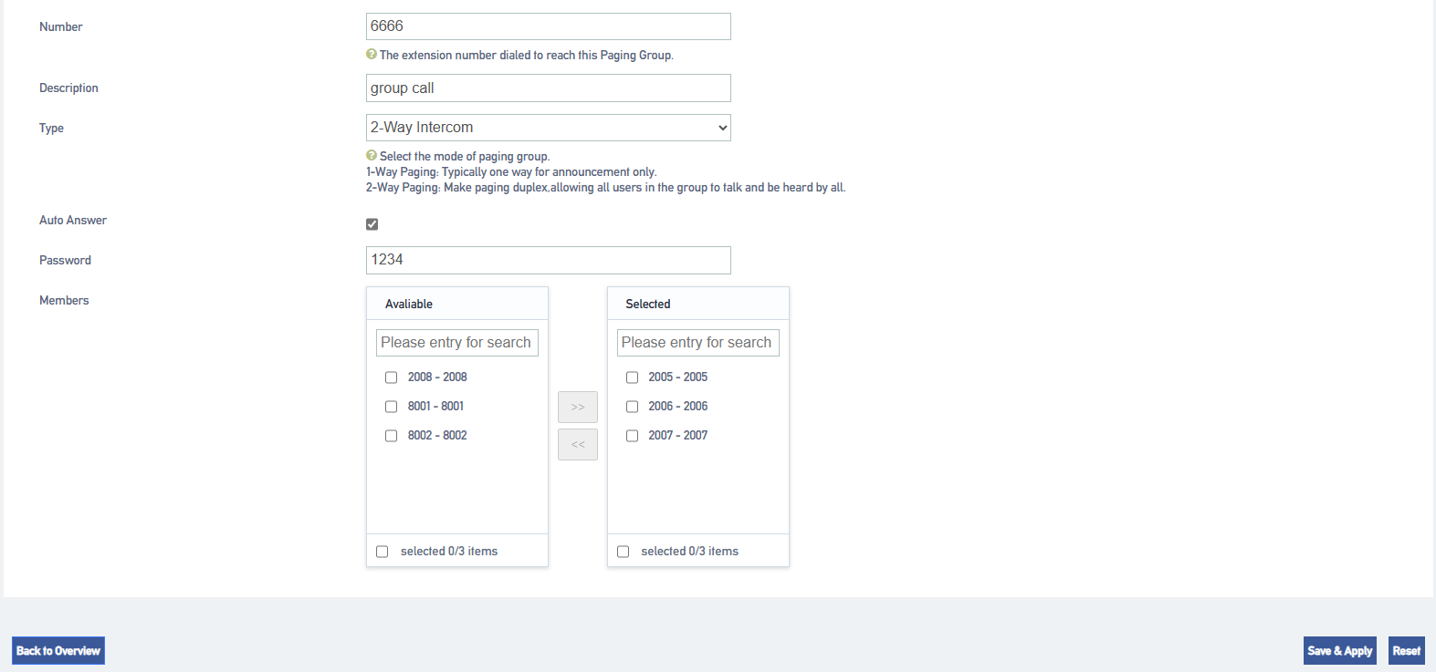
[Number]: Set the broadcasting phone number.
[Description]: describes the broadcast group to make it easy to distinguish between different broadcast groups.
[Type]: Select two-way intercom.
[Auto Answer]: optional. When enabled, extensions that support the auto broadcast function will be automatically taken off the air.
[Password]: Optional. After setting the password, users need to enter the password to dial the phone number of the broadcast group.
[Member]: Move the intercom group member to the selected box.
4.Click [Save & Apply].
When a user dials the number of this intercom group, the phones of the group members will automatically go off-hook and enter a multi-party call.
8.5.2 One-way paging
The one-way paging function of the radio is suitable for sending out notification announcements.
- Go to Call Feature -> Paging/Intercom and click [Add].
- Set up one-way broadcast groups.
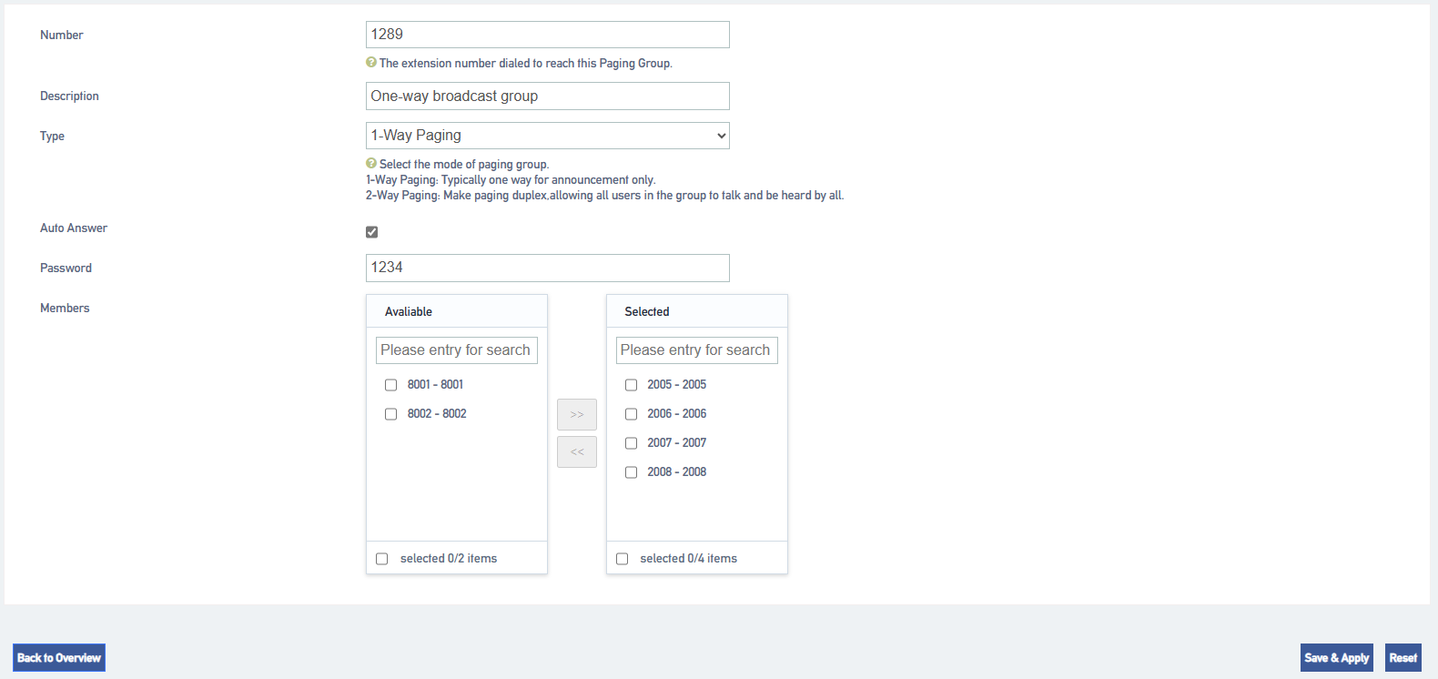
[Number]: Set the broadcasting phone number.
[Description]: describes the broadcast group to make it easier to distinguish between different broadcast groups.
[Type]: Select one-way paging.
[Auto Answer]: optional. When enabled, extensions that support the auto broadcast function will be automatically taken off the air.
[Password]: Optional. After setting the password, users need to enter the password to dial the phone number of the broadcast group.
[Members]: Move the intercom group members to the selected box.
3.Click [Save & Apply].
8.5.3 Automatic broadcasting
The IPPBX supports auto broadcast. This section describes how to set up an auto broadcast group.
- Go to Call Feature -> Paging/Intercom and click [Add].
- Set up an auto broadcast group.
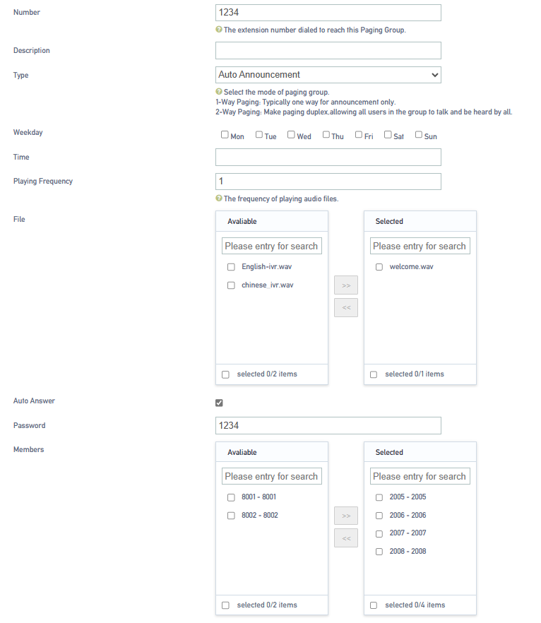
[Number]: Set the broadcasting phone number.
[Description]: describes the broadcast group to make it easier to distinguish between different broadcast groups.
[Type]: Select Auto Broadcast.
[File]: Select the audio file to play the broadcast.
[Auto Answer]: optional. When enabled, extensions that support the auto broadcast function will be automatically taken off the air.
[Password]: Optional. After setting the password, users need to enter the password to dial the phone number of the broadcast group.
[Members]: Move the broadcast group members, to the already selected box.
3.Click [Save & Apply].
8.6 Call following
Call following, which can be used to quickly find people. When a user has several work locations and all are configured with extensions. There are other users who want to find you but don’t know which workplace you are at, at this point you can use the Call Follow Who feature so that all of the user’s extensions at all locations will ring.
Set up call following:
- Go to “Call Feature ” -> “Fine Me” click [Add].
- On the [Fine Me] configuration screen, change the following settings:
| set up | descriptive |
| (telephone) extension | Select the extension that needs to be configured for call following. |
| descriptive | Describe who it is, with call following configured, so users can quickly identify it. |
| ringer timeout | Sets the member ringing time in seconds for call following when an incoming call is received. |
| members | Select Call Follow Ringer Member. |
8.7 OneShot
The One Call feature allows you to configure multiple extensions and cell phone numbers for a single user. When a customer service call to your company’s location on the extension, may be you are on a business trip, in order not to miss the customer calls, you can set up a number of extensions, bound to your cell phone number, so that out of the business can also answer the call, to avoid missing important calls.
One Pass Setup:
- Go to “Call Feature ” -> “Follow Me” Click [Add].
- On the No. 1 Configuration screen, change the following settings:
| set up | descriptive |
| (telephone) extension | Select the extensions that need to be configured with a OnePass. |
| descriptive | Used to back up descriptions for quick user identification. |
| ringer strategy | [Group Ringing]: The system will ring all idle extensions at the same time until the incoming call is answered.
[Random]: The system will randomly ring an extension. [Rotation]: The system will ring members in sequence. |
| ringing interval | After an extension rings for longer than the ringing interval, the next extension will ring. |
| numbers | Select the number. |
| overtime pay | All extensions ring for an accumulated time, and when this setting is exceeded, the entire call will be terminated. |
8.8 Speed dialing
Extension users may have phone numbers that they need to call frequently. You can set up speed dialing on the IPPBX system to make it easier for extension users to call the numbers of their frequently used contacts. Users need to add speed dial prefix (default *99) to use the speed dial function, for example, if the speed dial code is 1, you need to dial *991 to dial the number for frequent contacts.
8.8.1 Setting up speed dialing
- Go to Call Feature -> Speed Dial and click [Add].
- Speed dial settings.
| set up | clarification |
| (telephone) extension | Select the extension for which you need to set up speed dialing. |
| shortcut number | You can set up speed dial numbers. |
| Destination address | Destination phone number. |
3.Click [Save & Apply].
8.8.2 Speed Dial Feature Codes
The default speed dial prefix is *99. go to Advanced Feature -> Feature Code to change the speed dial prefix.

8.8.3 Speed Dialing Example
If the speed dial number set by the user is an outgoing number, you also need to consider the outgoing route set by the IPPBX. Example: the outgoing route must start with 9 in order to dial the outgoing number, otherwise the speed dial will fail.
The callout routing rules are as follows:
- Outbound mode: _9.
- Delete prefix digits: 1
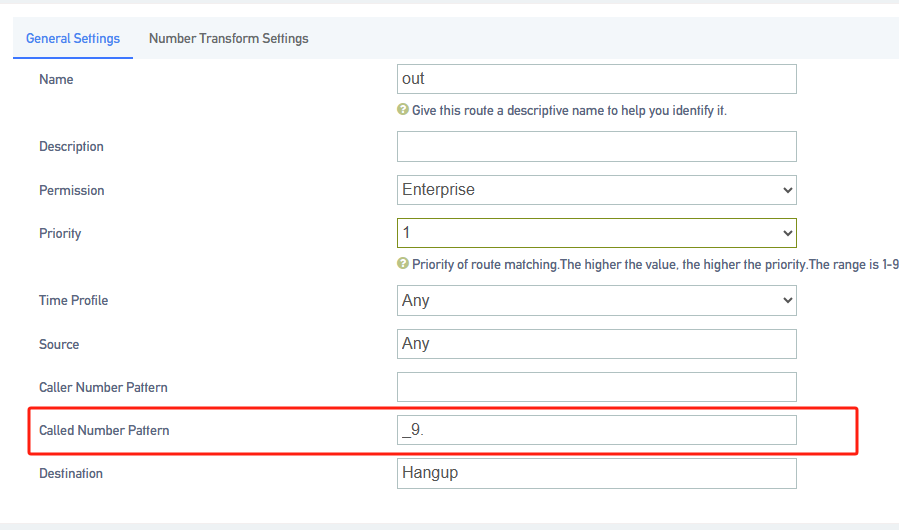

To quick call the destination number 12345678, you need to set the phone number to 912345678.

8.9 DISA
DISA, users call IPPBX through the outside line, when the destination of the inbound route is DISA, users can use IPPBX to dial the outside line number. When users are traveling, sometimes they need to make a call to the company’s customer service, but they want to use the company’s phone number to call the customer service, at this time, DISA can be a good solution to this problem.
8.9.1 Configuring DISA
DISA Configuration Steps:
- Create DISA.
- Go to Call Feature -> DISA and click Add.
- In the pop-up dialog box, set the DISA rule.
| set up | clarification |
| name (of a thing) | Set the name of the DISA. |
| cryptographic | Set the password that users need to enter when using DISA.
Note: When using DISA, be sure to set a password to prevent stolen calls. |
| Response timeout (s) | The response timeout period, default is 10 seconds.
Note: Do not set the response timeout too short, otherwise the call will be disconnected before the user enters the number to be dialed when using DISA. |
| Key press timeout (s) | Timeout for waiting for input DTMF, default is 5 seconds. |
| routing authority | Select the routing privileges for this specified extension. |
- Click [Save & Apply] when the configuration is complete.
- Set up outbound routing for DISA purposes.
- Go to Call Control -> Inbound Routers and click [Add or Edit].
- Inbound Routing Configuration page. the destination of the inbound route is a DISA. and select the created DISA.
- Click [Save & Apply].
- When users dial the trunk number bound to [Inbound Routers] through their cell phones, they will hear the prompt to enter the password, and after entering the password correctly, they will hear the dial tone, and then dial the outbound number, which can be called out through the outbound routing specified by DISA.
Note: For outgoing numbers dialed by users through DISA, the dialed number must satisfy the outgoing call rules of the outgoing call routing in order to make normal outgoing calls.
8.9.2 Wake-up calls
Alarm clock function for reminding users to avoid missing important things. After the user sets the alarm on the designated extension, the extension will ring at the specified time.
- Go to “Call Feature” -> “Wake-up Call” and click [Add].
- On the Alarm Clock Settings page, configure it.
| set up | clarification |
| (telephone) extension | Select the extension for which you need to set an alarm. |
| wake-up call | The alarm clock’s ringing tone. |
| timing | Set the time for the alarm to ring. |
| wake-up call cycle | How long after the alarm goes off, how often does it go off again. |
| Number of wake-up calls | Number of times the bell is rung. |
| Number of days awake | How many days to ring from current. |

3.Click [Save & Apply].
8.10 T.38 Fax settings
8.10.1 Fax to Mail
Configure fax-to-email:
- Go to Advanced Feature -> SMTP to make sure that SMTP is configured correctly and the mailbox function can be used normally, otherwise IPPBX cannot send faxes to users’ mailboxes.
- For extensions using fax, make sure you have filled in your e-mail address.
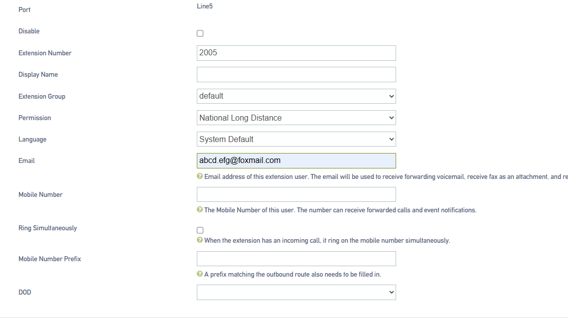
- Set up inbound routing, fax to email.
- Go to Call Control -> Inbound Routers , click [Add or Edit]. In the Inbound Routers Destination field, select Fax to Email.

- The user can also send faxes to the user’s mailbox by, enabling the fax detection function.

8.11 Demolition calls
The Forced Disconnect Call feature allows an authorized user to forcibly disconnect another user from an active call. Before a user can use this feature, you need to configure the Forced Disconnect Call feature code and assign permissions to that user.
8.11.1 Configuring Forced Calls
procedure
- Log in to the IPPBX webpage, go to Advanced Feature -> Feature Code, and search for Forced Calls.
- Setting up a forced call signature code.
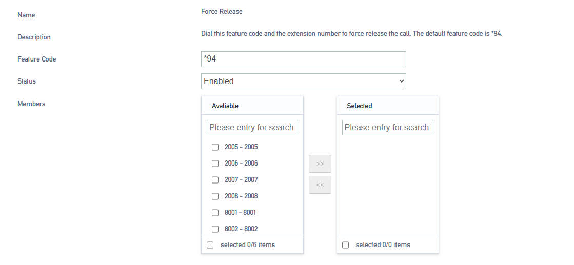
a.In the Feature Code field, modify the forced demolition feature code.
Tip: Feature codes must not be renumbered with other feature codes.
b.In the [Status] field, select Enable.
3.In the Members column, select which extension members can use the razing permission.
4.Click [Save & Apply].
Usage
Authorized users can dial [Feature Code + Called Number] on their own phones to force disconnect the call from the specified extension.
Forced insertion example
Employee A (extension 2000) and Employee B (extension 3000) are on a call; Administrator C (extension 1000) has an urgent matter to check with Employee A. In this case, Administrator C can forcibly disconnect Employee A’s call and call Employee A again.
- pre-conditions
Administrator C needs to have permission to force a call.
2.procedure
To force the disconnection of Employee A (extension 2000), perform the following steps:
Administrator C dials [Feature Code + Called Number].
In this example, the administrator dials *942000.
3.Implementation results
Employee A and Employee B’s calls are forcibly disconnected and the user will hear the following prompts respectively:
- Administrator C hears the tone “Demolition successful”.
- Employees A and B hear a busy signal.
8.11.2 Call back when busy
When the extension dialed by the user is in positive busy or no answer, you can enable the Call Back in case of Busy function. When the called party is idle, the IPPBX will call the caller back and re-establish the call, thus reducing the waiting time of the caller.
Tip: The Call Back in case of Busy function is only applicable to the scenario of internal extension dialing each other.
8.11.3 Busy Callback Example
Siu Lo and Siu Ming are not in the same office area; Siu Lo’s extension number is 1000 and Siu Ming’s extension number is 1001.
- Ro dialed the number for Ming.
- At this time, Ming was on a call and was unable to answer Luo’s call, and Luo’s call request was hung up.
- Xiao Luo called [*371001] at this time to turn on the callback function in case of busy.
Note: After the call is successfully booked, to cancel the appointment, dial [*0371001].
- The IPPBX will ring Ming first after his call has ended and is idle.
- Ming answers the incoming call and IPPBX calls Lo.
- Lo answered the call and the call was established successfully.
8.11.4 Busy callback feature code
Log in to the IPPBX webpage and go to Advanced Feature -> Feature Code to view or change the busy callback feature code.
Default busy callback feature code:
- Enable busy callback: *37
- Cancel busy callback: *037
8.11.5 Calling for mooring
Users can temporarily hold the current call and hang up during a call. The IPPBX will play background music to the party on which the call is held, and then the user can retrieve the held call from another phone.
8.11.6 Call Parking Settings
Going to Advanced Feature -> Feature Code, users can change the feature codes for Call Parking. Below are the default call parking settings.

8.11.7 Using Call Parking
The user can dial this feature code on the handset to park the incoming call to the system-assigned parking number; the system will play the parking number after successful parking, and the call can be resumed by dialing this parking number on other handsets (*6701). The default for this feature code is *6.
- During the call, the extension user dials *6; the system plays the tone “701”, indicating that the current call is parked at number 701.
- The user of this extension dials *6701 on another phone to retrieve the previous call.
9 Advanced Functions
9.1 General settings
9.1.1 General settings
Limit the length of calls to all extensions when dialing an outside number.
-
- [City Call Duration Restriction]: Restricts the maximum call duration for city calls.
- [Domestic Call Duration Limit]: Limit the maximum call duration for domestic calls.
- [International Call Duration Limit]: Limit the maximum call duration for international calls.
- Maximum number of forwarding times for call forwarding]: To avoid the call being stuck in a dead loop state, causing the whole device to jam. The default is 10 times.
9.1.2 Signal tone
DTMF Code Length ( ms ): set the length of the audio sent by the FXO relay in ms. default is 120ms.
Signal tone standard: Select your country or a country or region that uses the same signal tone (signal tone includes: dial tone, busy tone, ringback tone, etc.).
9.1.3 Dialing detection
The device needs to match the detected DTMF number with the number bit chart during the call to determine whether the collection is finished to shorten the delivery time. The configuration is as follows:
- Click Advanced Feature->Preferences->Dialing Detection to set the rules related to number bitmap.
-
- Analog extension pickup without dialing timeout:
-
If no number is dialed within the time from off-hook to the time specified in this parameter, the device will abandon this call and play a busy tone to prompt the user to hang up. The default is 15 seconds.
-
-
- No dialing timeout between bits:
-
If the next number key is not dialed within the time from the dialing of the previous number key to the time set in this parameter, the device will consider the user’s dialing finished and call out the dialed number. The default is 5 seconds.
- Numbered bitmap rules:
| Matching rules | clarification |
| X | Represents any number from 0 to 9. |
| Z | Represents any number from 1 to 9. |
| N | Represents any number from 2 to 9. |
| [123459] | Represents any number in parentheses, e.g., in this example, the numbers: 1,2,3,4,5,6,7,8,9. |
| Wildcard “.” | Represents any numeric number with a length greater than 0. For example, “_9011.” represents that any number beginning with 9011 (excluding 9011) will be added to the list; |
| Wildcard “!” | Represents the end number match, which is an optional wildcard to be used when determining the length of the number.
For example, when only four-digit numbers need to be matched, you can enter “_XXXX!” to indicate that all four-digit numbers will be added to this list. |
2.Number Bitmap Configuration
Example 1: A user wants to dial an IPPBX internal extension without waiting and dial out immediately. You can configure it as follows
Note: The Number Bitmap Only function is only for the FXS channel.
9.1.4 DTMF detection sensitivity
Go to Advanced Features -> Preferences -> DSP Settings to configure DTMF information.
| name (of a thing) | clarification |
| DTMF signal duration | This parameter specifies the DTMF signal duration in milliseconds from the FXO port. The default value is 100 milliseconds. It should normally be set in the range of 50 ~ 150 milliseconds. |
| DTMF inter-code signal spacing | This parameter specifies the time in milliseconds between DTMF signals from the FXO port. The default value is 100 milliseconds. It should normally be set in the range of 50 ~ 150 milliseconds. |
| Minimum hold time for DTMF signals | The minimum duration of the valid DTMF signal. The valid range is 32 to 96 milliseconds and must be a multiple of 16, the default value is 48 milliseconds. The larger the value set the tighter the detection |
9.2 Call logging and recording
9.2.1 Call Recording
IPPBX supports call recording function. internal and external calls, queues, ring groups, IVRs, conference calls of IPPBX can be recorded. The call recording function is very practical, which can help the company to examine employees, record important voice information, and also provide effective legal evidence for business disputes.
Setting up call recording
Before using the recording function, users need to connect an external storage device to the IPPBX and set the storage path for recording files.
To set the recording file storage location.
- When accessing an external storage device, it is best to format it once.
Notes:
- TF card support format NTFS, FAT32.
- USB supports formats NTFS, FAT32.
- Access external storage devices to the hardware interface of the IPPBX.
- Go to Advanced Feature -> Storage to check whether the external storage device is accessed successfully.
- Select the storage location for the recording file.
a.Go to Advanced Feature -> CDR and Recording -> Record and select your external storage device.
b.Click [Save & Apply].

To set up internal call recording.
- Go to Advanced Features->CDR and Recording->Record and check Internal Call Recording.
- In the Extension to Record field, select the extension you want to record to the Selected box.
Note: Extensions with intercom turned on will also be recorded when talking to an outside number.
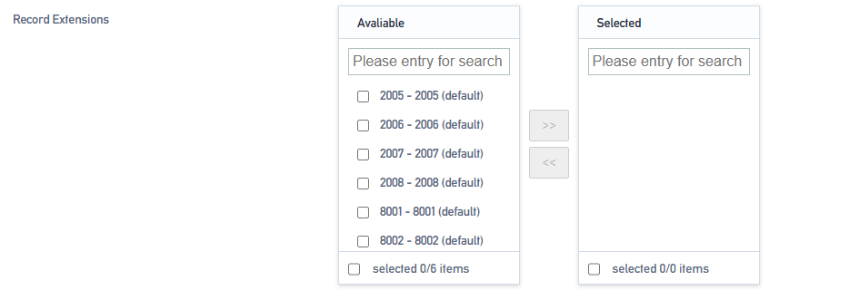
3.Click [Save & Apply].
To set up external call recording.
- Go to Advanced Feature -> CDR and Recording -> Record.
- In the [Extension to Record] field, select the trunk to be recorded in the Selected box.
- Note: Selected trunks, when talking to an internal extension, are also recorded.
- Click [Save & Apply].
Web Storage Recordings
Automatic cleaning of recording files.
The IPPBX automatically deletes the oldest recording files when the storage utilization of the external storage device exceeds 80%.
Enable automatic cleanup reminders.
Go to Advanced Feature -> Storage -> Auto Cleanup to change the default auto cleanup settings for automatic recording files based on recording usage.
| set up | clarification |
| Maximum utilization of recording storage devices (%) | Recording files are saved up to a maximum percentage of storage space, the default is 80%. Exceeding it deletes the oldest data and always saves the newest data. |
| Maximum number of days to keep recordings | Maximum number of days to save the recording file, if exceeded, the oldest data will be deleted and the latest data will always be saved (0 means no limit). |
Managing audio files.
Search for audio files.
- Log in to the IPPBX webpage and go to Advanced Feature -> CDR and Recording.
- On the [CDR and Recordings] screen, select the search time period, the start time and the end time that you need to find.
- Set other search criteria.
- Click [Query].

Download searchable audio files.
- Search for call logs on the CDR and Recordings screen that have recording files.
- Click [Download Button] to download the searched recording file.

Deleting individual recording files.
Under the recording file option, click [Delete button] to delete the recording file.

Delete all recording files.
Tap [Empty] on the [CDR and Recording] page to delete all the recording files, as well as the call logs.

9.2.2 Call records
Users can check the call logs and recordings of all extension users on the IPPBX web page. A call record contains a variety of information about a call, including time, call duration, source number, destination number, and so on.
Check call records.
- Log in to the IPPBX webpage and go to Advanced Feature -> CDR and Recording.
- Set the time to query the call records for this time period.
- Set other search criteria according to your needs.
- Click [Query].
Call records that match the search criteria are displayed on this page.
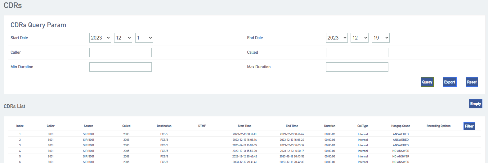
Manage call logs.
- Export Call Logs: Click the Export button to export all call logs.
- Delete call logs: Click Clear to clear all call logs.
9.3 Cues
9.3.1 Tone Options
Set the IPPBX prompt tone related settings.
Go to Advanced Feature -> Voice Prompts -> Prompt Preference to change the settings of the relevant prompts.
| set up | descriptive |
| system alert | The user can change the system tone as required. |
| Called Number Invalid Tone | Set the tone when the call number is empty. |
| Trunk Busy Tone | Set the tone when the relay is busy. |
| Call Failure Tone | Set the tone to be played when an outside line is unreachable or other abnormalities prevent an outgoing call. |
9.3.2 Waiting for music
Once the caller is on voice wait, the system will play waiting music.
The system has a default waitlist default. you can add waitlist files to the default list, or you can add a new waitlist.
- Setting the waiting music
- Go to Advanced Feature -> Voice Prompts -> Music On Hold and click [Add].
- Enter the waiting music.
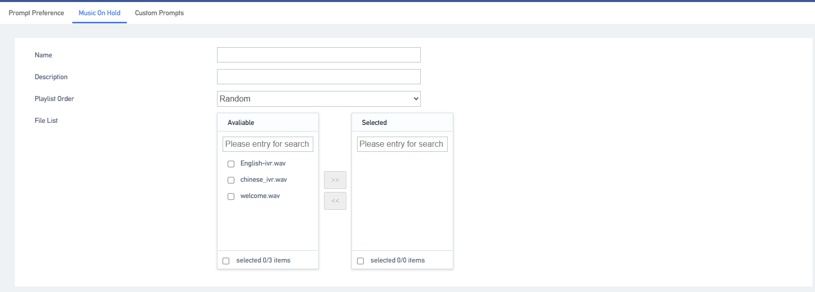
[Name]: Set the name of the waiting music.
[Description]: Add a description to the waiting music, easy to find and recognize.
[Play Order]: The order in which the music is played in the waiting music playlist.
[File List]: Select the cue file to be played.
Tip: Waiting for the music to play files that need to be uploaded in the cue options.
9.3.3 Customizing Beeps
- Upload a customized tone
- Go to Advanced Feature -> Voice Prompts -> Custom Prompts and click Import.
- In the pop-up window, select the produced voice file.
Note: Uploaded files must meet the voice file requirements. Currently only 8000hz, 16 bit, mono, wav format is supported.
The audio file format, which can be converted by audio conversion software, can be converted.
9.4 SIP Settings
9.4.1 Basic SIP Settings
- Click Advanced Feature -> SIP -> General Settings to enter the [General Settings] page.
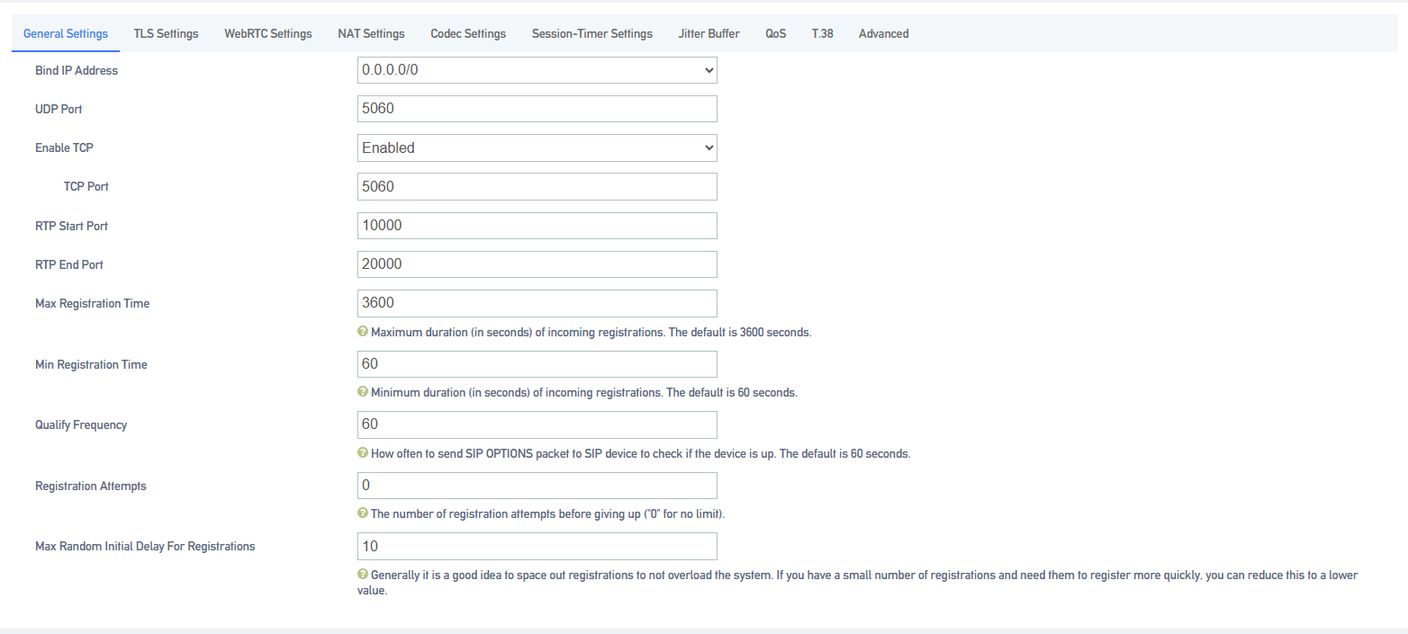
2.General settings
| set up | instructions |
| Bind IP address | Usually no setup is required, and it is bound to all network ports by default. |
| Random SIP UDP ports | Enable random ports, the IPPBX can only be used for registration and cannot be registered by other devices. |
| UDP port number | The port number to be filled in when registering to the IPPBX via UDP. |
| Enabling TCP | Open the TCP protocol. |
| RTP start port | The port on which voice calls are made; the starting port defaults to 10000. |
| RTP end port | The port on which voice calls are made; the end port defaults to 20000. |
| Maximum registration time period | The maximum time period allowed to register to the IPPBX. The default is 3600 seconds. |
| Minimum registration time period | The minimum time period allowed to register to the IPPBX. The default is 60 seconds. |
| Qualify packet frequency | The frequency with which the system periodically sends SIP OPTIONS packets to the phone to verify that the phone is online. The default is 60 seconds. |
| Number of registration attempts | The number of times a message requesting registration is sent before the SIP registration is abandoned. |
9.4.2 NAT Settings
Network Address Translation (NAT) is used to translate an intranet address and port number into a legitimate public network address and port number to establish a session to communicate with a public network host.
NAT Type: IPPBX supports 2 types of NAT configuration, [Public IP Address] and [Domain Name].
- application scenario
There are two scenarios where NAT needs to be configured:
- SIP extensions are registered to the IPPBX via [Remote Registration].
- Connect IPPBX and other devices via [SIP Trunk].
Note: If a one-way call occurs and the SIP extension is unable to hang up for a long time, it is usually due to NAT configuration errors.
- Configuring NAT for Public IP Addresses
If the user IPPBX is connected to the local LAN and the router connected to the IPPBX has a fixed [Public IP Address], then the user can configure NAT with [Public IP Address].
- Map the relevant ports on the router.
- Open the IPPBX web page and go to Advanced Features -> SIP -> NAT Settings.
- Select [Public IP Address] in the [NAT Type] field.
- The user configures NAT for the IPPBX according to the network environment.
[External IP Address]: Enter the fixed IP address and SIP external port of the router.
[External Port]: Fill in the external port for route mapping.
[Local Network Address]: Enter the local IP address and subnet mask. When the system is located behind a firewall or NAT, you can set the local network address here in the format such as “192.168.0.0/255.255.0.0” or “10.0.0.0/255.0.0.0”.
Note: If you have more than one local network address, go ahead and add additional IP addresses.
5.Click Save to restart the IPPBX.
- Domain Configuration NAT
If the router connected to the IPPBX does not have a fixed public IP address, then you can configure NAT with a domain name.
- Configure DDNS on the IPPBX or set up DDNS on the router.
- Map the relevant ports on the router.
- Log in to the IPPBX web page and go to Configure Advanced Feature -> SIP -> NAT Settings.
- In the [NAT Type] drop-down list, select [Domain Name].
- Configure NAT according to your network environment.
[Domain Name]: Enter the domain name and SIP external port of the IPPBX.
[External Port]: Fill in the external port for route mapping.
[Local Network Address]: Enter the local IP address and subnet mask. When the system is behind a firewall or NAT, you can set the local network address here in the format of “192.168.0.0/255.255.0.0” or “10.0.0.0/255.0.0.0”.
Note: If you have more than one local network address, go ahead and add additional IP addresses.
6.Click Save to restart the IPPBX.
9.4.3 SIP Codecs
Codec is a compression or decompression algorithm used to transmit voice packets over a network.
Codec selection:
IPPBX supports the following voice codecs: [G711], [alaw], [ulaw], [GSM], [H264], [G722], [G726], [G729], [iLBC].
Caveats:
-
-
- The SIP phone and the IPPBX must select an identical voice code, otherwise the call will not be established.
- When using video calls, users need to select the same video encoding for both IPPBX and SIP phones: [H264] or [VP8].
- Selection of iLBC The iLBC codec supports two modes: 20ms and 30ms frame mode. For better voice quality, you need to set the iLBC mode according to the SIP endpoint.
-
9.4.4 TLS Settings
| set up | clarification |
| Enable TLS | Whether TLS is enabled. |
| TLS port | TLS port, default is 5061. |
| Authenticating TLS servers | Whether to verify the server certificate when IPPBX is used as a client. If you do not have a CA certificate for this server, set this item to No to skip the server certificate verification for connection. The default is no. |
| Authenticating TLS Clients | Whether or not the IPPBX will validate client certificates when acting as a server. If set to Yes, the IPPBX will request and verify the client certificate. The default is no. |
| TLS Client Methods | Specifies the TLS connection protocol initiated when the IPPBX is used as a client, the default is tlsv1. |
9.4.5 Session timer
The SIP session timer is used to determine if a session has been terminated. Both user agents and proxy servers can determine whether a session is alive or not by using the SIP session timer.
| set up | clarification |
| session timer | The session timer determines whether a session is alive or not by periodic session refresh. the IPPBX supports the following three modes. The default is no.
|
| Session period (s) | Maximum refresh interval in seconds. |
| Minimum session refresh interval (s) | Minimum refresh interval in seconds. The set value must not be less than 90 seconds. |
9.4.6 Jitter buffer
In poor network environment, it may cause loss of transmitted packets in a call, thus appearing that both parties can’t hear what the other party is saying in a call. When jitter buffer is turned on, it intentionally delays the packets transmitted by both parties to overcome the effects of network jitter, thus giving users a good call experience.
Jitter buffer setting
Go to Advanced Features->SIP->Jitter Buffer to enable and change the jitter buffer settings.
| set up | clarification |
| Enable jitter buffer | Allows the use of jitter buffering in the sender SIP channel. |
| implementation method | Sender SIP channel jitter buffer implementation:
[Fixed]: set the jitter buffer time to a fixed value, default is 200ms. the system collects the sound and sends the sound to the destination with a fixed jitter buffer size. [Adaptive]: Allow the jitter buffer time to vary within a certain range, the default is 0ms-200ms. after the system collects the sound, it sends the sound to the destination with the adaptive jitter buffer size. |
| Buffer size (ms) | Maximum value of the adaptive jitter buffer time. |
9.4.7 T.38
| set up | clarification |
| T.38 Maximum bit rate | T.38 Maximum Bit Rate. |
| Re invite package without adding T.38 attributes | If enabled, the SDP does not add the T.38 attribute in the Re INVITE package. |
| Correction of errors | Set whether to enable fax error correction. |
9.4.8 Advanced SIP Settings
| set up | clarification |
| Allow RTP to be re-invited | The system redirects RTP media streams from the caller to the called by default. There are some devices that do not support this feature, especially when the device is located behind a NAT. |
| user agent | Allows the user to change the User-Agent field. |
| 100rel | Whether the 100rel protocol is supported. |
| Send Remote Party ID | Sets whether to send the Remote Party ID in the SIP header field.
This option is only available for internal calls. If you want to set it for external calls, please set it in “Advanced” of SIP trunks. |
| Send P Asserted Identify | Sets whether to send P Asserted Identity in the SIP header field.
This option is only available for [Internal Calls]. If you need to set it for external calls, please set it in “Advanced” of SIP trunk. |
| Send Diversion ID | Sets whether to send Diversion in the SIP header field; when enabled, the value of Diversion is the extension number.
This option is only available for internal calls, if you want to set it for external calls, please set it in “Advanced” of SIP Trunking. |
| Multi-computer Full Busy Mode | If this option is checked: when one of the terminals registered at the same time for an extension is busy, the other terminals will be restricted from calling in, but can still call out.
If unchecked: when one terminal is busy, other terminals can still make inbound and outbound calls. |
9.5 Voice mail
IPPBX supports sending voicemail and fax to email. This article explains how to set up voice mailbox and how to send voice mailbox to email.
9.5.1 Mailbox settings
Go to Advanced Feature->Voicemail to configure your mailbox.

[Maximum number of voice messages per folder]: Maximum number of messages allowed for each extension, default 20.
[Maximum Message Time]: The maximum time for a single message, default 120 seconds.
[Minimum Message Time]: Messages less than the length of time will be deleted, default 3 seconds.
[Delete Voice Messages]: when enabled, automatically delete voice messages that have been sent to the mailbox. It is not enabled by default.
[Storage Location]: Setting the message storage location. Internal device, SD/TF, USB.
[Subject]: The name of the subject of the e-mail to be sent.
[Attribution]: Attribution for sending emails.
Note: SMTP must be configured for voicemail messages to be sent to mailboxes.
9.6 SMTP
If you want to enable sending voicemail to your own mail, then SMTP must be configured.
Click Advanced Feature -> SMTP to enter the SMTP configuration page.

9.6.1 SMTP configuration
| functionality | clarification |
| Enable Mailbox | Enable Mailbox |
| SMTP server settings | Fill in the SMTP service address, you can fill in the IP address, you can also fill in the domain name common SMTP server address format: SMTP.XXXX.com.
Example.
|
| SMTP port number | Fill in the port number of the SMTP mailbox server:
The filling of the port number depends on the rules of the mailbox you are using. Take QQ mailbox for example: If the tls/ssl connection is not enabled, transfer port 25. If the tls/ssl connection is enabled, the transfer port is 465. |
| Connecting using TLS | Enable TLS transport connections. |
| Using the STARTTLS protocol | It can be turned on if the mailbox server supports it, and needs to be turned off if it doesn’t. |
| SMTP server authentication method | Select the login authentication method.
|
| user ID | The account used to log in to your mailbox. |
| cryptographic | Fill in the authorization code for the mailbox. |
| SMTP Test | Verify that the mailbox is available. |
9.7 Feature Codes
Users can, at their extensions, dial feature codes. Feature codes can be used to enable, disable, and query some features on the IPPBX.
Go to Advanced Feature -> Feature Code to view and change feature settings.
9.7.1 Default Feature Codes
| Query WAN port address | *158 |
| Query LAN port address | *159 |
| Query extension number | *114 |
| Enable Call Waiting | *51 |
| Cancel Call Waiting | *50 |
| blind switch | *03 |
| Ask for a transfer | *3 |
| Enabling unconditional transfers | *71 |
| Elimination of unconditional transfers | *071 |
| fail to materialize | *72 |
| fail to stop a meeting and try to move it | *072 |
| Enable no-answer transfer | *73 |
| Cancel no-answer transfer | *073 |
| Enable Do Not Disturb | *78 |
| Remove Do Not Disturb | *79 |
| Listen to voice messages | *2 |
| Language Mailbox Menu | *02 |
| listener mode | *90 |
| eavesdrop | *91 |
| Force insertion of a listener | *92 |
| speed dial | *99 |
| Phone Login | *105 |
| phone logout | *106 |
| extension roaming | *88 |
| peer group connection | *4 |
| Designated pick-up | *04 |
| call to berth | *6 |
| activate a busy callback (computing) | *37 |
| Close the door and call back. | *38 |
| demolish by force | *94 |
| Alarm settings | *56 |
| three-way call | ## |
| Call Follow | *25 |
| phone self-test | *116 |
| certification billing | *66 |
9.7.2 Modifying feature codes
Users can modify the value of the feature code by themselves. Note: The device needs to be rebooted after modifying the feature code.
The user follows the procedure below to make changes:
- Click Advanced Feature -> Feature Code to enter the Feature Code page.
- Users can use the query function to find the feature code they need to set and click [Edit].
- When the modification is complete, click [Save & Apply].
9.7.3 Three-way calls
This article will explain the use of three-way calling
Member A and member B are on a call, at this time member A can press ### to form a mini conference. After that, both members A and B can press # + the extension number to be invited to continue to invite other members to join the call, and the maximum number of members to be invited is 20.
9.8 Storage
IPPBX supports local storage, external storage and network storage. After the storage device is added, users can store call recordings, voice messages, call logs and other information to the designated storage location.
9.8.1 Storage types
[SD Card] (Max. 256GB)
USB 2.0] (Maximum 2TB)
[Hard disk] (Max. 2TB)
[Web Disk Mounting]
9.8.2 Storage location
You can set your own storage location for both call logs and recordings, and voice messages.
9.8.3 Storing the Settings List
Users can check the usage of [Local Storage], [External Storage], and [Network Storage] in the Storage Settings list, as well as determine whether the mount is successful.
The Storage Settings list displays the storage device’s, [Total Capacity], [Utilization], [Remaining], and [Storage Type]. The following figure shows the storage settings.

Note: Before using a physical storage device, you need to format the device.
9.8.4 Adding network disks
Users can create a shared folder on a Windows PC and then add a network disk to the IPPBX to mount the shared folder to the IPPBX. the network disk can be used to store auto-record files, voice mail and one-click recordings, logs, call logs, and backup files.
- Configuration example
This article describes how to mount a shared folder on Win10 computer in IPPBX.
1. Create a shared folder on your Windows computer.
a. Create a folder on your computer and name the folder [English and numbers only].
b. Right-click the folder and select Properties -> Sharing.
c. Click Share (S)… , set the share properties. Add the share user Everyone and change the permissions to Read/Write and click Share.
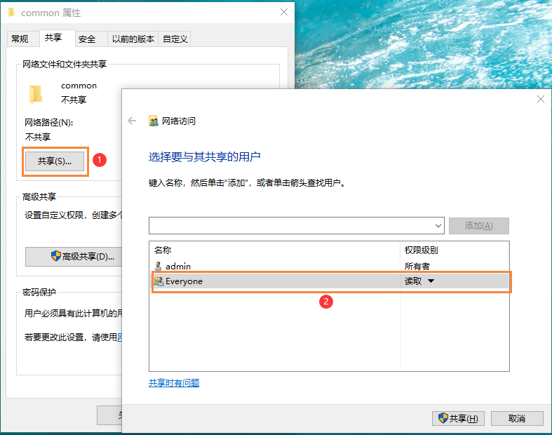
d. Click Advanced Sharing (D)… , set the Advanced Sharing properties. Check Share this folder and set Allow all permissions, click OK.
2. Turn off your computer’s firewall feature, otherwise other users may not be able to access the shared files.
a. Go to Control Panel -> Windows Defenser Firewall on your Windows computer.
b. Click Enable or Disable Windows Defenser Firewall.
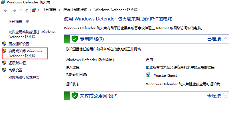
c. Select Turn off Windows Defender Firewall.
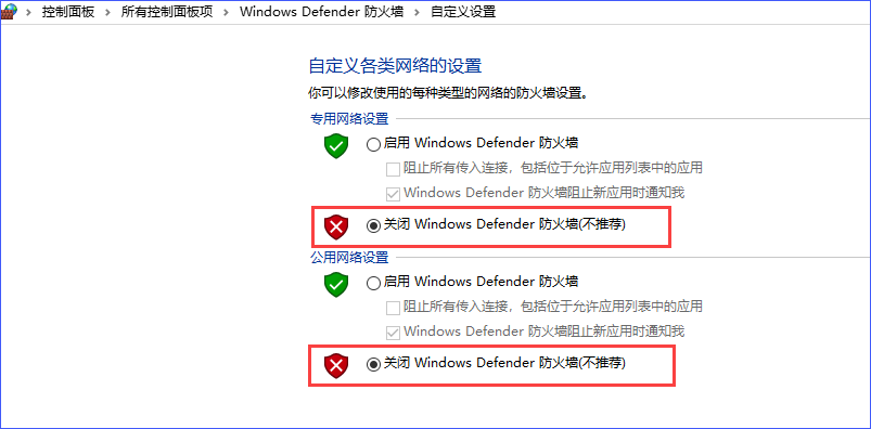
d. Click OK.
3. Add a network disk to the IPPBX web interface.
a. Go to Advanced Feature -> Storage -> General and check Network Disk.
b. On the Network Disks page, fill in the following configuration:
[IP Address]: Fill in the IP address of the shared computer.
[Shared Name]: Fill in the name of the shared folder.
[Connected User Name]: Fill in the access user name of the computer where the shared folder is located.
[Password for connection]: Fill in the access password of the computer where the shared folder is located.
[Workgroup]: Optional. If your network disk has a workgroup set up, please fill in the correct group name here, otherwise it can be left blank.
Samba Version]: Select the Samba version of the network disk, and the default is that the system will match automatically.
[Tip]: If the mount fails, try changing the Samba version.
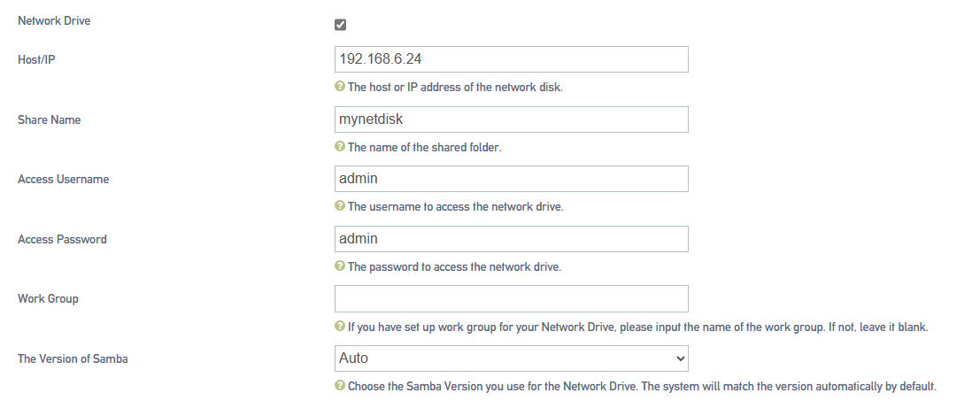
c. Click [Save]. If the configuration is successful, the storage device list displays information about this network disk .
- common problems
- How do I find out the user name that accesses a shared folder?
a.On the computer where the folder has been created, press [WIN key + R key] to open the Run window, type cmd and then Enter to enter the Command Prompt.
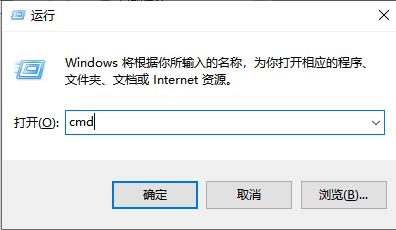
b.In the Command Prompt window, you can view the user name of the current computer.
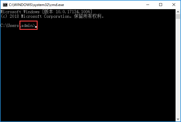
2.How do I set up a network disk when my computer access password is empty?
- If the computer does not have an access password set, we recommend that you set an access password for the computer and fill in that password when setting up the IPPBX network disk to try to remount the network disk.
- If you want to remove access to the share password, you can check the computer’s Turn off password protection sharing settings (path: Control Panel -> Network and Sharing Center -> Advanced Sharing Settings).
When setting up the IPPBX network disk, the user name and password are left blank to mount successfully.
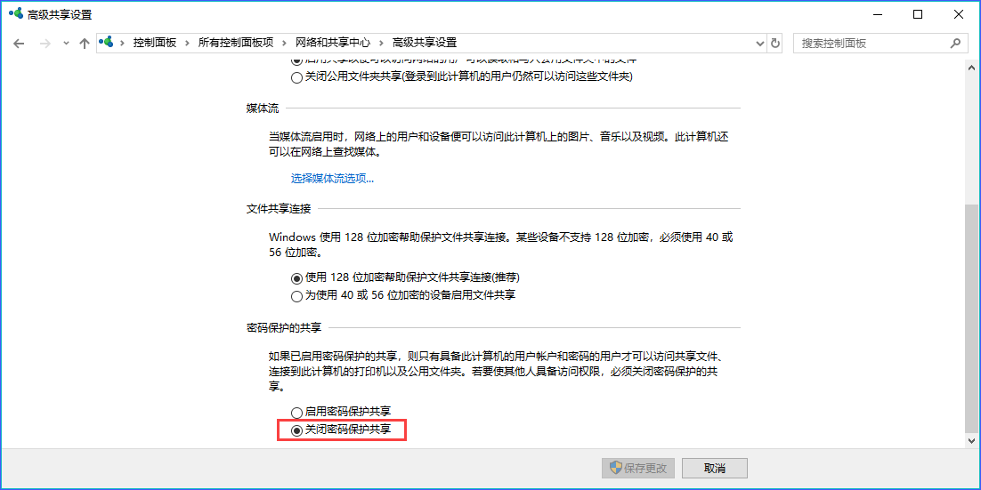
Note: Some computers with password protected sharing turned off and the username and password left blank may not mount successfully. Eventually, you have to enable the password protection and set the password. And disabling password protection is not supported for security reasons.
3.Other reasons for the problem of not being able to mount the netbook.
- The current version of [samba] protocol that WIN10 can mount only supports 2.1.

- The version of [samba] protocol that can be mounted by Windows server 2003 supports only [1.0].
- Windows server 2008 can mount the [samba] protocol version, support automatic, [1.0], [2.1].
- The version of [samba] protocol that can be mounted by Windows server 2012 supports [Auto], [1.0], and [2.1].
- Windows server 2019 The version of the [samba] protocol that can be mounted, supporting [2.1].
9.8.5 Automatic cleaning
In order to avoid the situation, the storage is full, resulting in the subsequent information can not be stored. It is recommended that users set up the auto-clean function, which can help users automatically clean up system files, including call logs and voice messages.
Go to Advanced Feature -> Storage -> Auto Cleanup to set the maximum number of files to be stored and the maximum time to be stored. When the storage number of these files reaches the set maximum value, the system will automatically clean up the files.

Note: Old data will be deleted when the maximum number of entries is exceeded, and the old data deleted here includes call logs and corresponding call recordings.
| Automatic cleaning of call logs | |
| Maximum number of articles saved | The maximum number of call logs to be saved, beyond which the oldest data is deleted and the latest data is always saved. |
| Maximum number of days saved | Maximum number of days to save call logs, beyond which the oldest data is deleted and the latest data is always saved (0 means no limit). |
| Automatic cleaning of recording files | |
| Maximum utilization of storage devices | Recording files are saved up to a maximum percentage of storage space, the default is 80%. Exceeding it deletes the oldest data and always saves the newest data. |
| Maximum number of days to keep recordings | Maximum number of days to save the recording file, if exceeded, the oldest data will be deleted and the latest data will always be saved (0 means no limit). |
9.9 Troubleshooting
9.9.1 Network packet capture
If there is an abnormality in SIP calls, SIP trunk calls, etc., users can use the network packet capture tool to get and download the packets, check the packet capture data, and determine the cause of the problem.
Users can follow the steps below to perform a network packet capture:
- Log in to the IPPBX webpage and go to Advanced Feature -> Troubleshooting -> Ethernet Capture Tool.
- In the [Interface] field, select the network interface for capturing.
- In the [Seconds, Packets] column, set the time to capture packets.
- In the [Filter] field, further select the target of the crawl.
- Click [Start]. The packet capture process requires the user to reproduce the problems that occur in the SIP trunk or extension.
- Click [End]. Stop catching packets.
- Click [Download]. Download the capture file to your local computer and open the file for analysis.
Note: It is recommended to open the analysis file with Wireshark software.
9.9.2 Recording tools
The recording tool can be used to detect FXO port and FXS port. In case of FXO port and FXS port problems, users can use the recording tool to detect the port and download packets to view the data.
- Go to Advanced Feature -> Troubleshooting -> Port Monitor Tools.
- In the [Line] field, select the port to be recorded.
- In the [Seconds, Packets] column, set the time to capture packets.
- In the [Filter] field, further select the target of the crawl.
- Click [Start].
- The IPPBX starts recording the trunk. While recording, the user needs to make a call using the problematic port to reproduce the problem.
- Click [End].
- Click [Download]. Download the recording file.
- Tip: It is recommended that users use Audition software to open recording files and analyze them.
9.9.3 Networks
- Ping (name)
The Ping command is based on the TCP/IP protocol and sends test packets from the local computer to a remote URL. You can use IP Ping to test whether IPPBX can access the target IP address.
- Log in to the IPPBX web page and go to Advanced Feature -> Troubleshooting -> Net -> Ping.
- Enter the destination IP address.
- Click [ping] and wait for the diagnostic result.
- You can view the diagnostic results when you are finished.
- TRACEROUTE (route tracing)
Route Trace displays the route path and calculates the delay time of packet transmission within a network segment.
- Log in to the IPPBX web page and go to Advanced Features -> Troubleshooting -> Network -> TRACEROUTE.
- Enter the target [hostname] name or [IP address].
- Click [TRACEROUTE] and wait for the result.
- When finished, you can view the recording tracking information.
10 System
10.1 System Management
10.1.1 Basic settings
- Change date and time
- Go to System -> System -> General Settings.
- In the [Time Zone] drop-down menu, select your local time zone.
- Setting the time synchronization.
NTP is used to provide time synchronization between routers, switches and workstations. Time synchronization is useful in that it allows related event records on multiple network devices to be viewed together, helping to analyze more complex failures and security events.
- Enable NTP client: When NTP client is enabled and the product is connected to the network, it will get the time from the NTP server.
Get the address of the server by default:
- time1.aliyun.com
- time2.aliyun.com
- time3.aliyun.com
- time4.aliyun.com
NTP Server: After checking NTP Server, this IPPBX can be used as an NTP server and other IPPBXs can get the calibration time from the NTP server of this IPPBX.
10.1.2 Language and interface
The user can set the language of the whole page. The default is Chinese. After modification, the whole WEB page will be changed to the language set by the user.
10.2 Management authority
In the management right page, users can change the login password of WEB page by themselves. The default initial password of the device is admin, for security consideration, users should change the password of WEB login page in the first time when they get IPPBX.

10.3 Security Center
10.3.1 Firewalls
Users are recommended to configure the network firewall after the initial IPPBX activation to avoid the IPPBX being invaded and stolen by criminals.
Firewall Rules
IPPBX is equipped with firewall rules by default, which can ensure that all devices in the same intranet can access IPPBX. users can also create firewall rules according to their own needs.
- Default firewall rules:
The IPPBX adds the following types of IP addresses or domain names to firewall rules by default:
local area network
- 10.0.0.0/255.0.0.0
- 172.16.0.0/255.240.0.0
- 192.168.0.0/255.255.0.0
2.Add firewall rules:
The following article will explain the function settings of the firewall, how to use firewall rules to [filter IP addresses], [ports], [domain names] and so on.
Go to System->Security ->Firewall and configure firewall rules.

[Name]: Set the firewall rule name.
[Direction]: Limit the filtering direction.
[Protocol]: Select the protocol targeted by the firewall rule.
- UDP
- TCP
- TCP + UDP
- ICMP
[Source Address]: Filter the source address for accessing the IPPBX.
[Source Port]: Filter the source port accessing the IPPBX, value range: integer from 1 to 65535. When the value is empty, the rule applies to any source port.
[Destination Address]: Perform data filtering on the destination IP address.
[Destination Port]: Number filtering on the destination port.
[Action]: Select the action of the firewall rule.
- Accept: The IPPBX will accept access from the specified address.
- Discard: IPPBX will ignore the access from the specified address and directly discard the data without any feedback. The discard action can prevent malicious attacks from detecting the server information of IPPBX, thus providing improved security of IPPBX system.
-
-
-
- Deny: The IPPBX will deny access to the specified address.
- No action: no restrictions.
-
-
-
10.3.2 Services
-
- WAN Port Access Web : When checked, you can access the web management page through the WAN port.
- WAN Port Access SSH : When checked, you can access SSH through WAN port.
- Prohibit being pinged: when checked, you will not be able to be pinged through by other servers.
10.3.3 SIP Automatic Defense
SIP automatic defense is not enabled by default. After enabling automatic defense, it can prevent a large number of connection attempts or malicious attacks. Example: After the IP extension authentication fails more than the number of times specified in this parameter (after the sip extension fills in the registration information, the number of consecutive failures exceeds the limited number of times), the device will refuse to register the IP extension and pull it into the IP address blacklist.
Go to System->Security ->SIP Auto Defense users can set up automatic defense rules according to the application.

[Enable]: When enabled, the setting takes effect.
[Verification Period]: Set the verification period. The unit is minutes, default 3 minutes.
[Maximum number of failures in the cycle]: In the verification cycle, when the user registers a SIP extension with an IP phone or a SIP softphone, the user will be locked out if the filled-in account number and password are wrong consecutively, and the number of errors is greater than the maximum number of failures in the cycle. The user will not be able to register to the device or continue to access the device after being locked.
[IP Address Lock Time]: The time the user is locked out, in minutes, default 30 minutes.
10.3.4 Automated Web Defense
When a user logs in to the web page and the number of wrong passwords exceeds the number of times specified in this parameter, the device will deny access from the user’s IP address. The user will be allowed to log in to the web page again only if the user changes the IP address or restarts the IPPBX.
Go to “System”->”Security”->”Web Auto Defense” users can change the auto defense rules.

[Enable]: When enabled, the setting takes effect.
[Verification Period]: Set the verification period. The unit is minutes, default 3 minutes.
[Maximum number of failures in the cycle]: During the authentication cycle, if the user logs into the web page and fills in the wrong account number and password consecutively, and the number of errors is greater than the maximum number of failures in the cycle, the user will be locked out. The user will not be able to register to the device or continue to access the device after being locked out.
[IP Address Lock Time]: The time the user is locked out, in minutes, default 30 minutes.
10.3.5 IP address blacklisting
IP addresses blocked by SIP Auto Defense and Web Auto Defense will be included in the IP address blacklist.
Enter “System” -> “Security ” -> “Blocked IP Address”, users can view the blacklisted IP addresses and the time of restriction, and users can also remove the blacklisted IP addresses themselves to lift the access restriction on IP addresses.

10.4 System logs
The IPPBX records user actions and saves them in the system log.
Log in to the IPPBX webpage and go to System -> System Log to search and view the user’s webpage system log.
10.4.1 Backup/Upgrade/Restore
Login to IPPBX webpage, enter System -> Backup/Flash Firmware, users can backup the current data. After the backup is completed, it will be downloaded to the download directory specified by the user. If users want to restore the previously backed up data, they only need to upload the previous backup file, then they can restore it back.
- Generating backup files
Users can create IPPBX backup files in the IPPBX web page.
- Go to System -> Backup/Flash Firmware -> Backup/Restore and click [Generate archive].

2.After generating the backup, the generated IPPBX backup file will be available in the browser’s download page.
- Restore Configuration
Users can upload backup files to IPPBX for data recovery.
- Go to System -> Backup/Flash Firmware -> Backup/Restore, and in the [Recovery Configuration field], click to select the file.
- Select the backup file you want to upload and click Open.

3.Click [Upload Archive]
4.After a successful upload, the system changes the configuration and reboots.
10.4.2 Flashing new firmware
Users can download the latest version of firmware through the website, and then log in to the WEB management page and upload the new version of firmware through the web page to upgrade the IPPBX.
- Log in to the IPPBX webpage, go to System -> Backup/Flash Firmware -> Flash new firmware image, and click to choose the file.
- Select the new version of firmware to be uploaded.
- Click on Flush Firmware.

Note: When flashing the firmware, remember to check [Retain Configuration File], if not, after upgrading the firmware, all previous configurations will be initialized. (By default, the Retain Configuration File will be checked)
4.After the upload is complete, the system will prompt for execution.
Note: Be sure not to lose power while refreshing or the system will be damaged.
5.Click Execute to go to the System Upgrade page.
Note: The upgrade will take about 5 minutes or so, and the device will drip once the upgrade is complete.
10.5 Safety Precautions
When registering sip extensions in the public network environment, the following modifications are recommended to prevent the user’s extensions from being stolen and resulting in huge telephone charges:
- Change the SIP extension password.
The registration password for SIP extensions is recommended to be [a mix of special characters + case + numbers] and the number of password digits is greater than 16.
2.Go to System -> Security -> SIP Auto Defense.
Enable SIP auto defense function. When SIP Auto Defense is enabled, if the number of wrong passwords entered during SIP extension registration exceeds the limit, the IP address of the SIP extension will be locked, making it impossible to continue registration.
3.Go to Advanced Feature -> SIP -> General Settings and change the default port for the transport protocol.
- UDP port: the default 5060 must not be used, modify it to a customized port.
- TCP Port: Do not use the default 5060, change it to a customized port.
- TLS port: the default 5061 must not be used, modify it to a customized port.
4.Go to Extension -> SIP Extension -> Advanced Settings.
- Modify the transport protocol of the SIP extension to TLS.
- Enable SRTP voice encryption.
- Enable user-agent registration authentication: when being registered by the FXS gateway, configure the content of the user agent according to the User-agent of the gateway.
- Initiate IP address restriction: When registered by an FXS gateway, configure the IP address limit range based on the gateway address and ensure that the gateway address does not change.
5.Go to System -> Security -> Service.
- Cancel WAN port access to the Web.
- Cancel WAN port access to SSH.
- Enable to disable being pinged.


