Digital Gateway L301 User Manual
1. Overview
1.1 Product Introduction
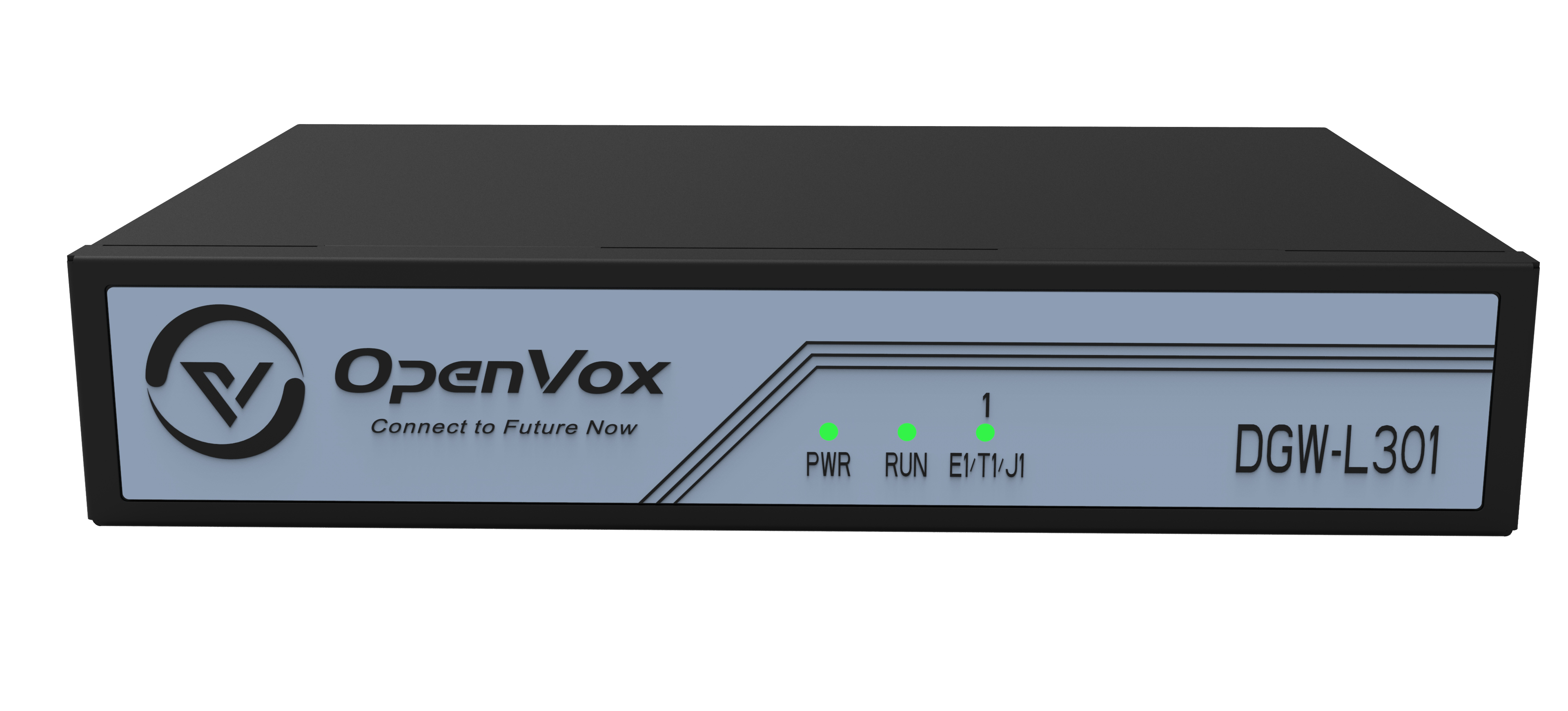
The OpenVox DGW-L301 gateway is an E1/T1 digital VoIP gateway that allows digital PSTN and ISDN hubs to connect to VoIP networks. It is a converged media gateway product. This gateway enables seamless integration between traditional telephone systems and IP networks, achieving seamless integration between VoIP PBX and ISDN. With its user-friendly GUI, users can easily configure their custom gateways. Additionally, secondary development can be performed via AMI (Asterisk Management Interface). The DGW-L301 T1/E1 gateway supports 1/2/4 software-selectable T1/E1/PRI interfaces and can handle up to 120 concurrent calls.
1.2 Simple Application
Figure 1-2-1 shows a simple application of the digital network series.
Figure 1-2-1 Application topology diagram
 1.3 Product Appearance
Figure 1-3-1 Product Appearance
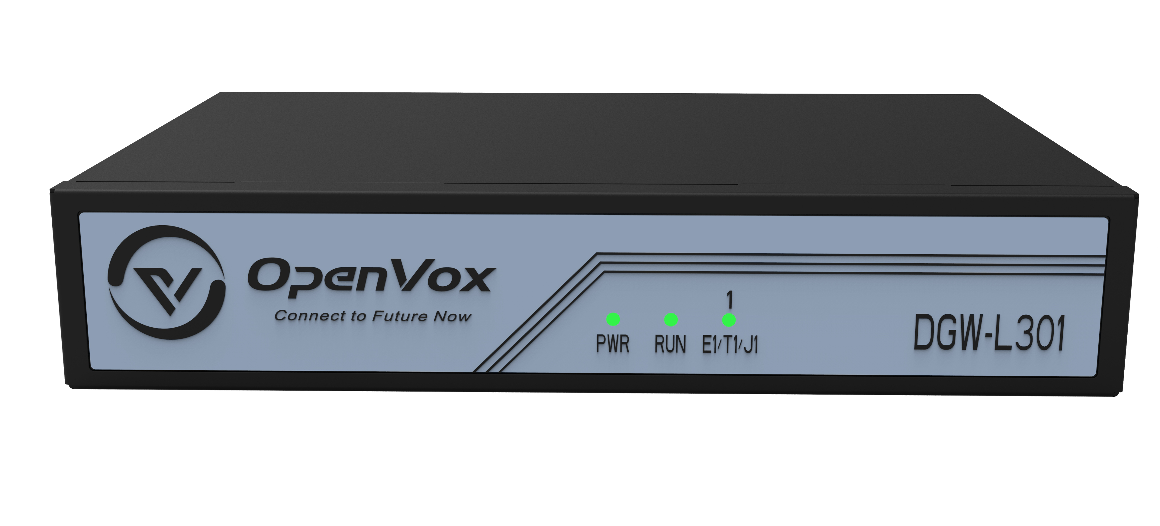

Figure 1-3-2 Front Panel

![]()

1-3-3 Back Panel
 1.4 Software Features
| L301 | |
| Telephone Port | 4 E1/T1 Ports |
| Profiles | Four profiles |
| Audio Compression | G.711A/U, G.723.1, G.729A/B, iLBC, OPUS, ARM, and ARM-WB |
| Fax | T.38 compliant with three types of fax relay up to 14.4 kbps and automatically switches to G.711 for fax transmission. T.38 fax relay uses V.17, V.21, V27ter, and V29 fax data pumps |
| QoS | Diffserve, ToS, 802.1 P/Q VLAN tagging |
| Telephone Features | Caller ID display or suppression, call waiting, blind transfer and consultation transfer, call forwarding, do not disturb, callback, paging, message waiting indicator light and interval alert tone, automatic dialing, flexible dialing rules |
| DTMF Mode | Flexible DTMF transmission mode, user audio interface, RFC2833, and/or SIP Info |
| SIP Signaling | SIP (RFC 3261) over UDP/TCP/TLS |
| Security | SRTP/TLS/SIPS, HTTPS, 802.1x |
| Upgrade and deployment | TFTP, HTTP, HTTPS |
| Network protocols | TCP/UDP, RTP/RTCP, HTTP/HTTPS, ARP, ICMP, DNS, DHCP, NTP, TFTP, PPPoE, STUN |
1.5 Hardware features
| L301 | |
| Port Type | RJ45 |
| Weight | 1200g |
| Dimensions | 232mm*152mm*45mm |
| Power Specifications | 12V 1A |
| Maximum Power | 3W |
| Operating Temperature Range | 0°C to 50°C |
| Storage environment humidity range | 10% to 90% non-condensing |
| Storage environment temperature range | -20°C to 70°C |
1.6 Software Features
Default IP: 192.168.6.65
Username: admin
Password: admin
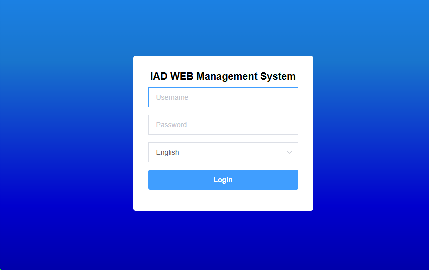
Connect the network cable to LAN1/LAN2, enter the default IP address in the browser, and enter the network settings to proceed with configuration.
Note: The default network mode for this product is bridge mode. Regardless of whether the network cable is connected to the WAN port or LAN port, the IP address remains the same.
Figure 1-6-1 Login Interface
2 Status
2.1 System Status
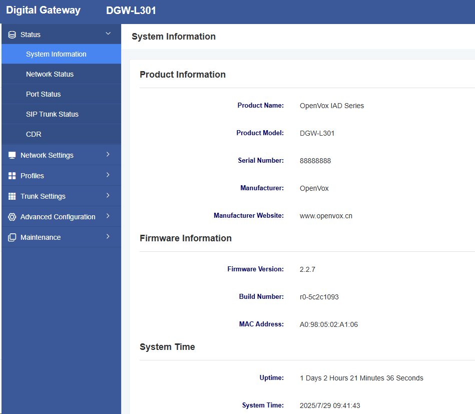
The “System Status” page displays product information, firmware information, system time, and resource usage.
Figure 2-1-1 System Status Display
 2.2 Network Status
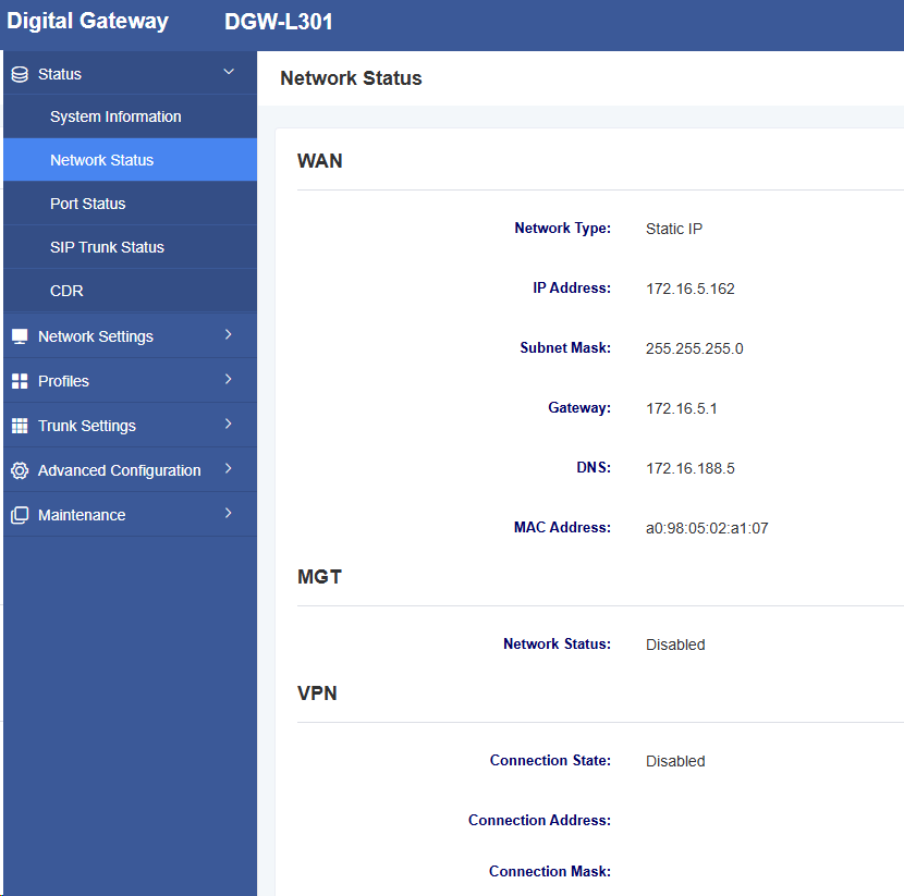
The “Network Status” page displays network status and VPN connection status.
Figure 2-2-1 Network Status
2.3 Port Status
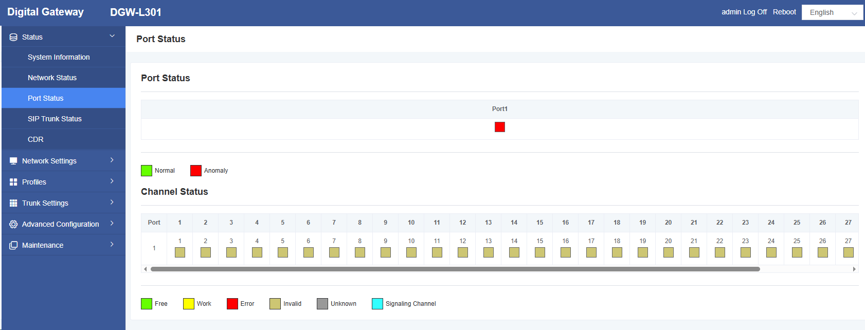
The “Port Status” page displays port status and channel status.
Figure 2-3-1 Port Status
2.4 SIP Trunk Status
On the SIP Trunk Status page, you can view the SIP trunk number, SIP signaling port, SIP user ID, authentication ID, registration status, IP direct routing table, and registration status.
Figure 2-4-1 SIP Trunk Status Page

2.5 CDR
On the CDR page, users can configure CDR settings and perform CDR queries.
Figure 2-5-1 CDR
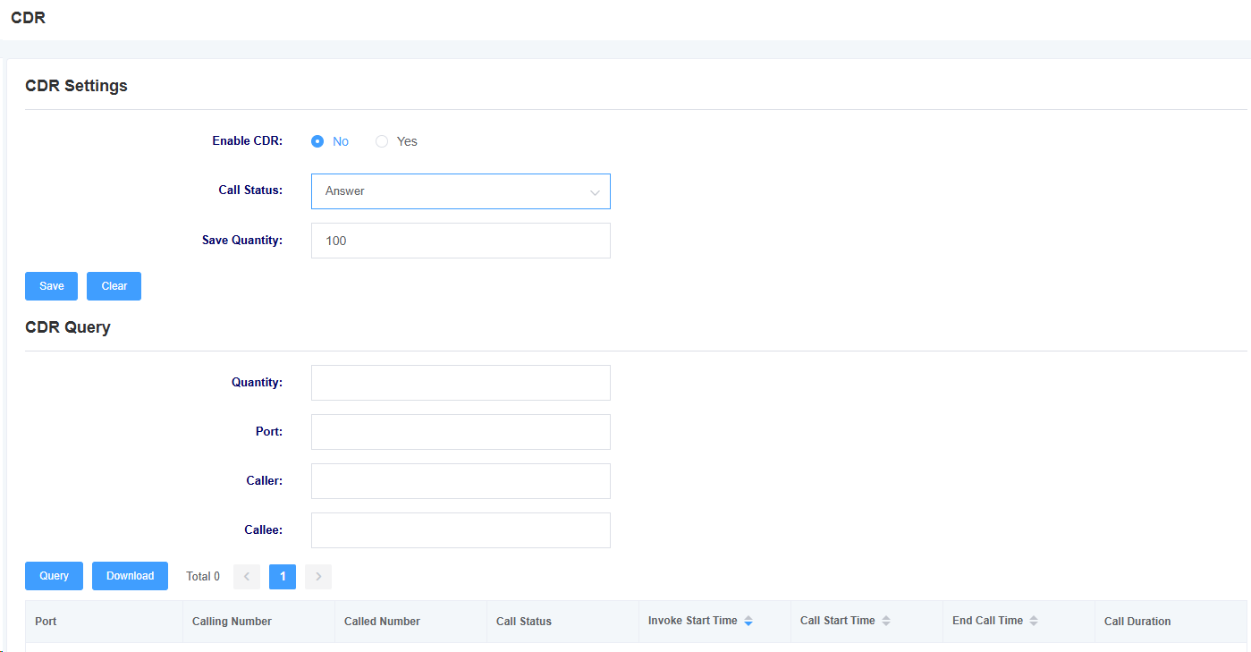
Note: CDR is only stored in memory and will be cleared upon reboot.
Table 2-5-1 CDR Options
| Option | Description |
| Enable CDR | This option selects whether to enable CDR |
| Call Status | Select the call status saved by CDR |
| Save Quantity | Set the number of CDR entries to save |
| Quantity | Select the number of CDR queries |
| Port | Select the port for CDR queries |
| Caller | Filter CDR query items by caller number |
| Calleee | Filter CDR query items by callee number |
3 Network Settings
3.1 Local Network
Figure 3-1-1 Local Network Interface
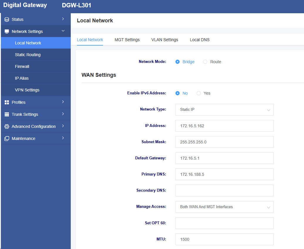
Table 3-1-1 WAN Settings Interface Parameter Description
| Option | Description |
| Network Mode | Select Device Network Mode: Bridge, Route |
| Enable IPV6 Address | Whether to enable IPV6 |
| Network Type | Select network type: DHCP, Static IP, PPPoE |
| IP Address | Set the device’s IP address |
| Subnet Mask | Set the device’s subnet mask |
| Default Gateway | Set the device’s default gateway |
| Primary DNS | Set the device’s primary DNS |
| Secondary DNS | Set the device’s secondary DNS |
| Management Access Options | Set web login restrictions |
| Set OPT 60 | Set OPT 60 |
| MTU | Set MTU, default value is 1500 |
Figure 3-1-2 Management Port Settings Interface
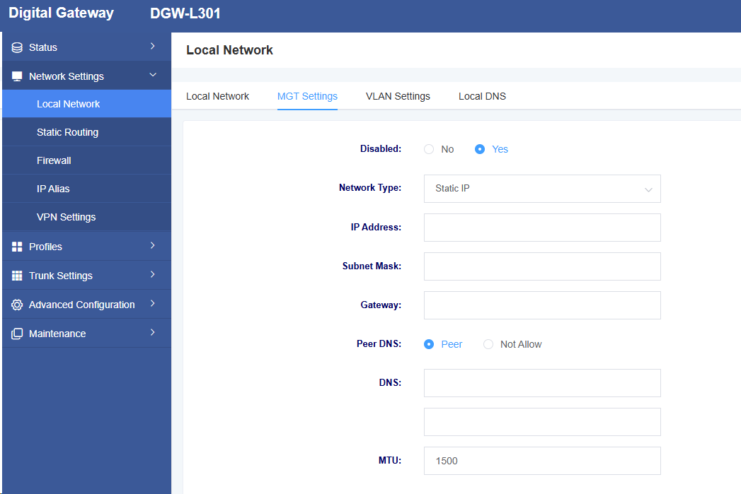
Table 3-1-2 Management Port Settings Interface Parameter Description
| Option | Description |
| Disabled | Whether to enable the management port |
| Network Type | Select the network type: DHCP, Static IP, PPPoE |
| IP Address | Set the device’s IP address |
| Subnet Mask | Set the device’s subnet mask |
| Gateway | Set the device’s gateway |
| Peer DNS | Select whether to allow peer DNS |
| DNS | Set the device’s DNS |
| MTU | Set MTU |
Figure 3-1-3 VLAN Settings Interface
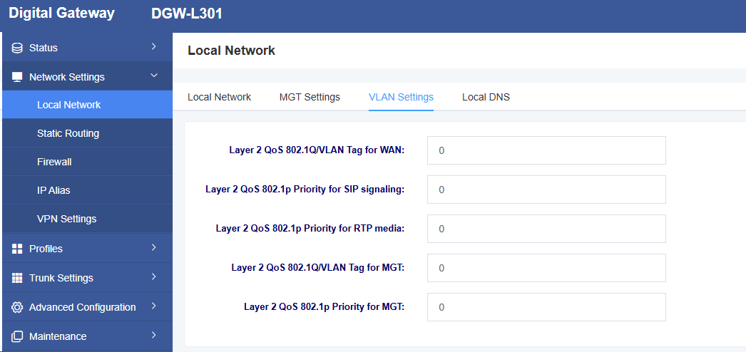
Table 3-1-3 VLAN Settings Interface Parameter Description
| Option | Description |
| Layer 2 QoS 802.1Q/VLAN Tag for WAN | Set WAN port tagging |
| Layer 2 QoS 802.1p Priority for SIP Signaling | Set SIP signaling priority |
| Layer 2 QoS 802.1p Priority for RTP media | Set rtp media priority |
| Layer 2 QoS 802.1Q/VLAN tag for MGT | Set management port tagging |
| Layer 2 QoS 802.1p priority for MGT | Set management port priority |
Figure 3-1-4 Add Local DNS Settings Interface

Table 3-1-4 Local DNS Interface Parameter Description
| Option | Description |
| Domain Name | Set the device domain name |
| Resolve IP | Set the IP to be resolved |
3.2 Static Routing
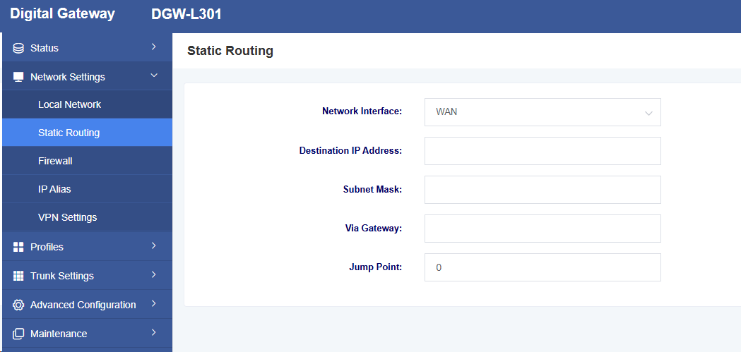
On the “Static Routing” page, the network interface, destination IP address, subnet mask, gateway, hop count, and operation for static routing are displayed. You can add static routing here. Click the Add button to add static routing.
Figure 3-2-1 Static Routing Interface

Figure 3-2-2 Add Static Routing Interface
3.3 Firewall
On the “Firewall” page, the firewall rules’ name, protocol, source network domain, source IP, source port, destination network domain, destination IP, destination port, and rule action. You can add firewall rules here to ensure the security of the device. Click the Delete button to delete a firewall rule, and click the Add button to add a firewall rule.
Figure 3-3-1 Firewall Interface
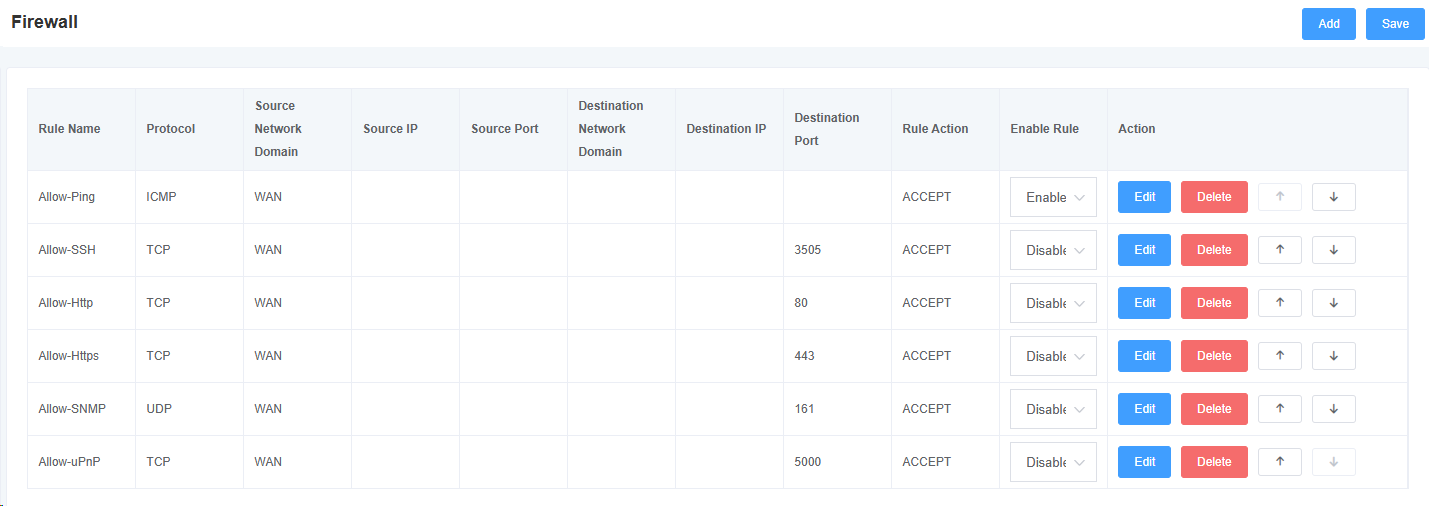
Figure 3-3-2 Add Firewall Rule Interface
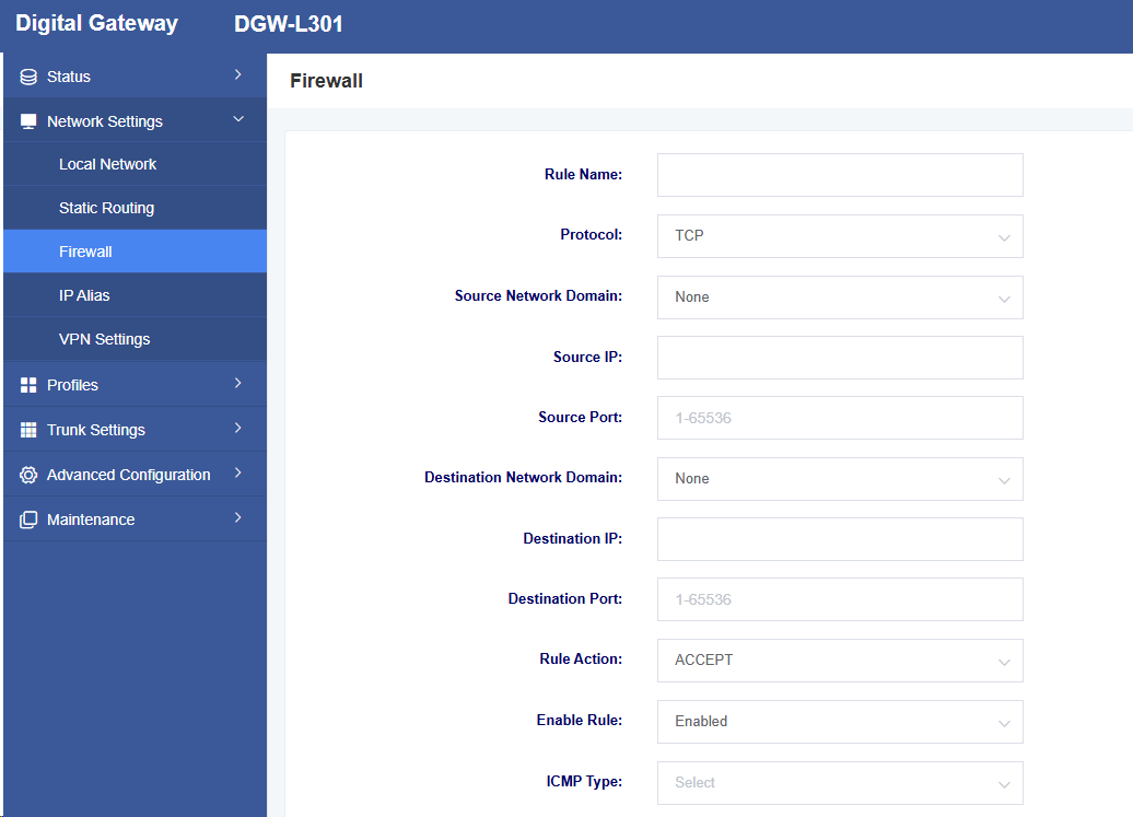
Table 3-3-1 Add Firewall Rule Parameter Description
| Option | Description |
| Rule Name | The name of the firewall rule |
| Protocol | The protocol specified by the firewall rule |
| Source Network Domain | The source network domain of the firewall rule |
| Source IP | The source IP defined by the firewall rule; if left blank, it applies to all IP addresses |
| Source Port | Defines the source port, with a range of 1-65535 |
| Destination Network Domain | The destination network domain of the firewall rule |
| Destination IP | The destination IP defined by the firewall rule. If left blank, it applies to all IP addresses. |
| Destination Port | Defines the destination port, with a range of 1-65535 |
| Rule Action | Defines the rule action, with options including ACCEPT, REJECT, and DROP |
| Enable Rule | Whether to enable rule |
| ICMP Type | Defines the ICMP Type |
3.4 IP Alias
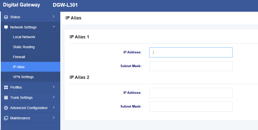
L301 supports configuring multiple IP addresses, which can be set in the IP alias interface.
Figure 3-4-1 IP Alias Interface
3.5 VPN Settings
Figure 3-5-1 OpenVPN Settings Interface
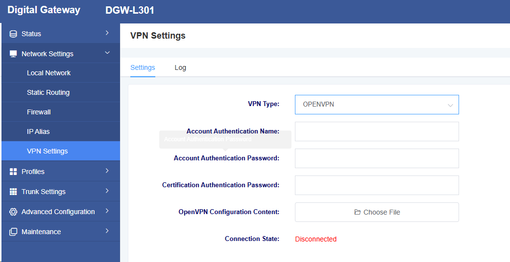
Table 3-5-1 VPN Settings Description
| Option | Description |
| VPN Type | You can choose to disable VPN or use OpenVPN/Softether VPN |
| Account Authentication Name | The authentication name used by OpenVPN |
| Account Authentication Password | The authentication password used by OpenVPN |
| Certification Authentication Password | Certification authentication password |
| OVPN Configuration Content | Upload the OpenVPN configuration file |
| Connection Status | Display the VPN connection status |
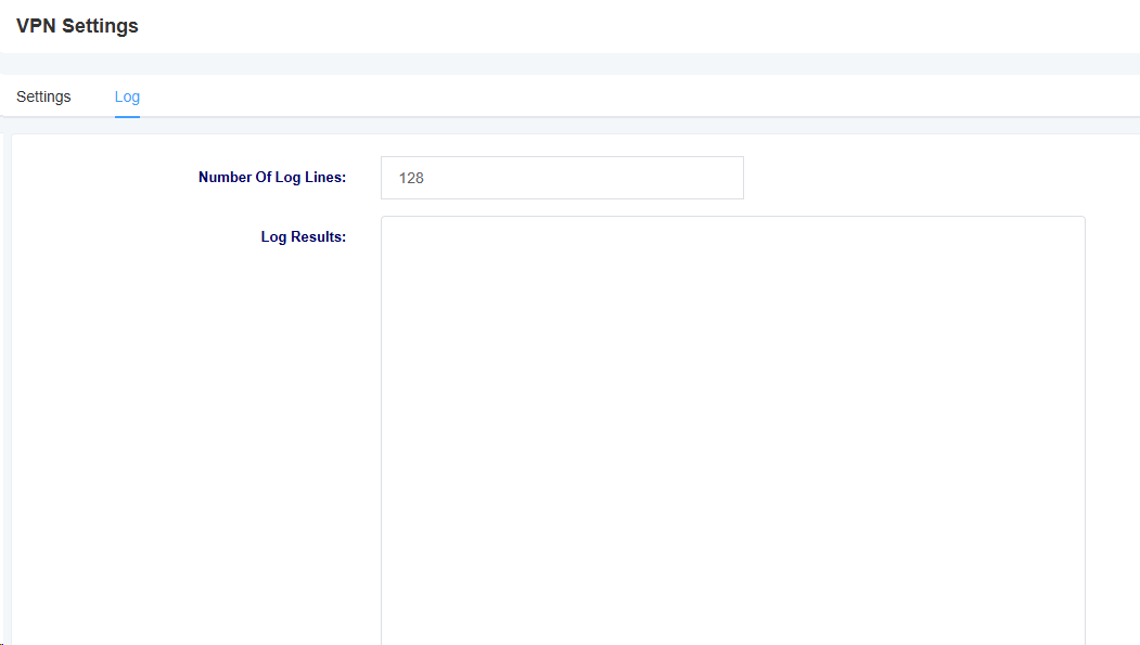
On the Log page, you can select the number of logs to display, then click the Query button. The logs will be displayed in the “Log Results” box.
Figure 3-5-2 Softether VPN Settings Interface
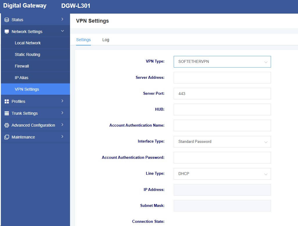
Table 3-5-2 Softether VPN Settings Description
| Option | Description |
| VPN Type | You can choose to disable VPN or use OpenVPN/Softether VPN |
| Server Address | The server address used by Softether VPN |
| Server Port | The server port used by Softether VPN |
| Hub | Hub Name |
| Account Verification Password | Enter the name |
| Interface Type | Select standard password or signed certificate |
| Account Verification Password | Enter the password |
| Certificate | Certification document |
| Line Type | Select Line Type: Static IP, DHCP |
| IP Address | Configure IP |
| Subnet Mask | Configure subnet mask |
| Connection State | Display the VPN connection status |
Figure 3-5-3 VPN Log Interface
4 Templates
The L301 provides a convenient SIP registration method, allowing users to easily apply pre-configured templates to SIP trunking. There are four templates available for configuration.
4.1 SIP Settings
Figure 4-1-1 SIP Settings
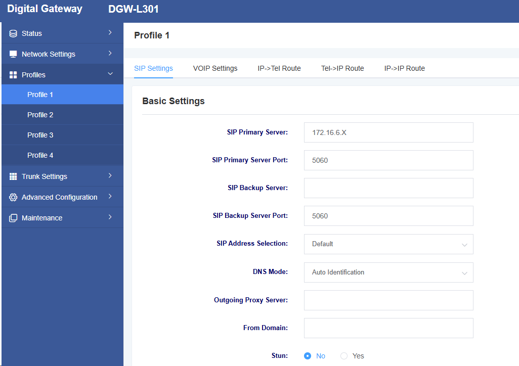
Table 4-1-1 SIP Settings Parameter Description
| Option | Description |
| SIP Primary Server | Set up SIP Primary Server |
| SIP Primary Server Port | Set up SIP Primary Server Port |
| SIP Backup Server | Set up SIP Backup Server |
| SIP Backup Server Port | Set up SIP Backup Server Port |
| SIP Address Selection | Select which network port to register the SIP service on |
| DNS Mode | Set DNS mode, selectable as automatic or use DNSSRV |
| Outgoing Proxy Server | Set outbound proxy server, the network will send signaling to this external proxy instead of directly to the peer. |
| From Domain | Set the domain name used to verify the peer |
| Stun | Select whether to enable STUN service |
Figure 4-1-2 SIP Settings
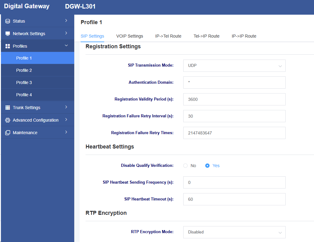
Table 4-1-2 SIP Settings Parameter Description
| Option | Description |
| SIP Transmission Method | Set the SIP transport method, with options including UDP, TCP, and TLS |
| Authentication Domain | Set the SIP registration authentication domain |
| Registration Validity Period | Set the registration validity period, default value is 3600 seconds |
| Registration Failure Retry Interval | Set the registration failure retry interval, default value is 30 seconds |
| Registration Failure Retry Times | Set the registration failure retry count, default value is 10 times |
| Disable Qualify Authentication | Whether disable Qualify authentication |
| SIP Heartbeat Sending Frequency | Set the SIP heartbeat packet transmission frequency |
| SIP Heartbeat Timeout | Set the SIP heartbeat packet timeout |
| RTP Encryption Mode | Enable RTP encryption |
Figure 4-1-3 SIP Settings
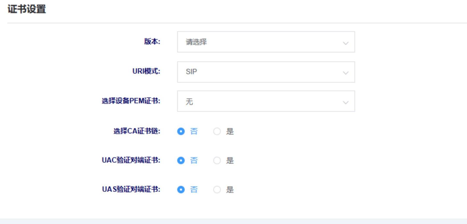
| Option | Description |
| Version | Select the certificate version. The device supports different versions of TLS, SSL, and SSH certificates |
| URI Mode | Select URI mode, supporting SIP and SIPS |
| Select The PEM certificate | Select device PEM certificate |
| Select The CA certificate chain | Select whether to enable CA certificate chain |
| UAC Verifies Paired-end Certificate | As the calling party, select UAC to use the phone as the refresher. Or select UAS to use the called party or proxy server as the refresher. |
| UAS verifies Paired-end certificate | As the called party, select UAC to use the called party or proxy server as the refresher, or select UAS to use the phone as the refresher. |
4.2 VOIP Settings
On this interface, users can set VOIP-related parameters.
Figure 4-2-1 VOIP Settings
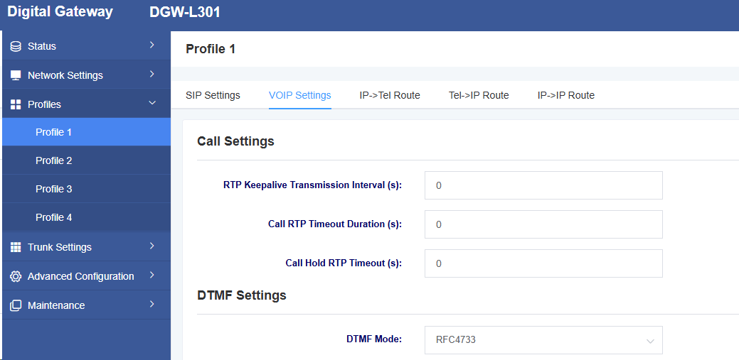
Table 4-2-1 VOIP Settings Parameter Description
| Option | Description |
| RTP Keepalive Transmission Interval | Set the RTP keepalive send interval |
| Call RTP Timeout Duration | Set the call RTP timeout |
| Call Hold RTP Timeout | Set the call hold RTP timeout |
| DTMF Mode | Set the DTMF mode, with options including RFC4733, inband, info, auto, and auto_info |
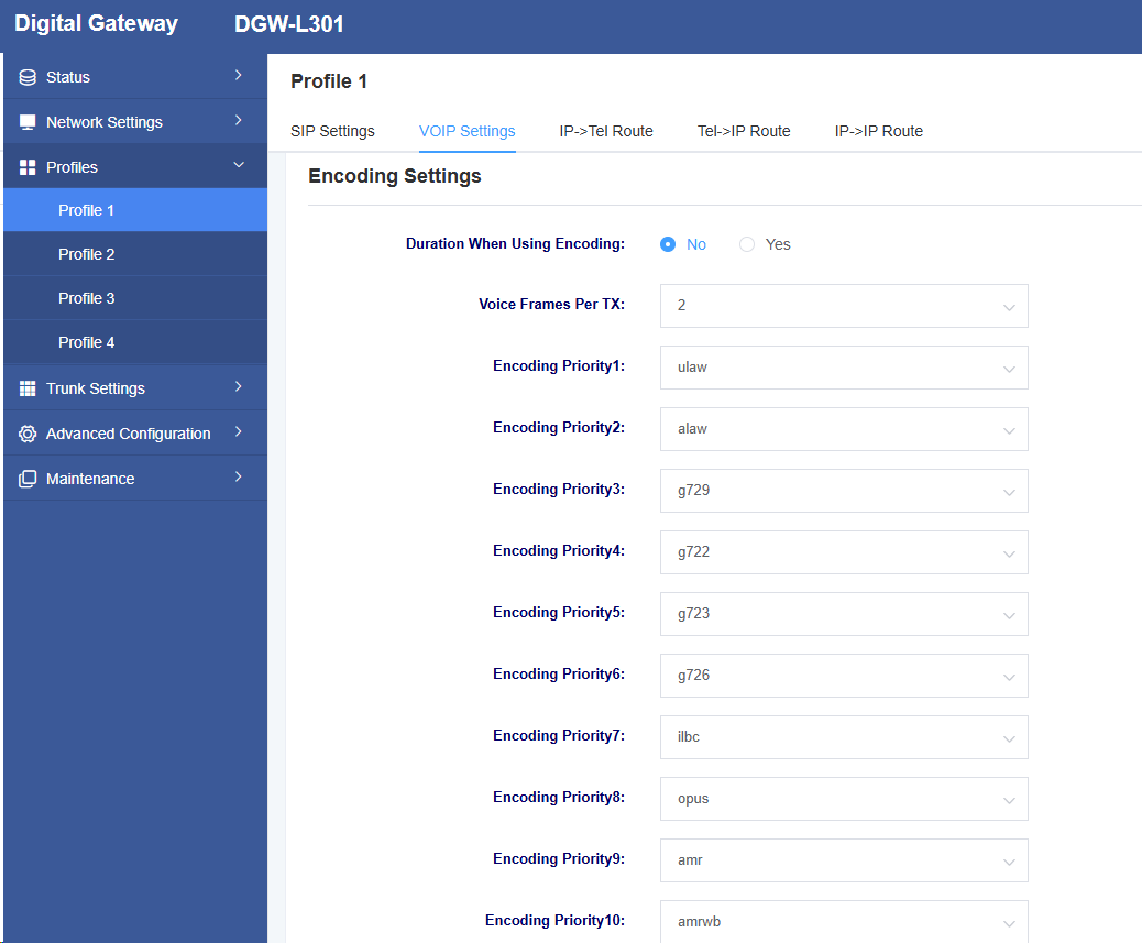
Figure 4-2-2 VOIP Settings

![]()
Table 4-2-2 VOIP Settings Parameter Description
| Option | Description |
| Duration When Using Encoding | Whether enable duration when using encoding |
| Voice Frames Per TX | Set Voice Frames Per TX |
| Encoding Priority | Set the encoding priority |
| Disable UDPTL | Select whether to disable UDPTL |
| UDPTL Error Correction | Select the UDPTL error correction method |
4.3 IP->TEL Routing
On this page, you can configure related routing settings.
Figure 4-3-1 IP->TEL Routing
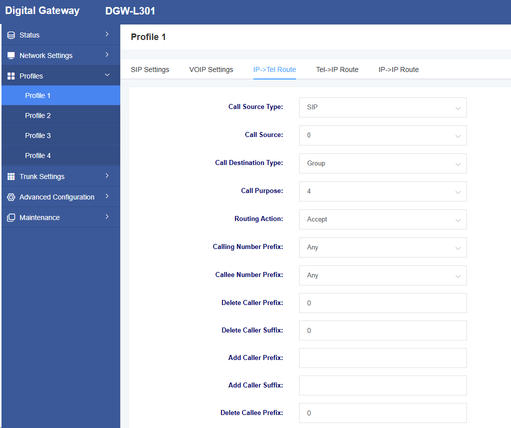
Table 4-3-1 IP->TEL Routing Parameter Description
| Option | Description |
| Routing Failed Call Destination Type | Whether enable routing failed call destination |
| Routing Failed Call Destination | The destination to which the call is redirected in case of failure |
| Call Source Type | The type of the call source device |
| Call Source | The call source device |
| Call Destination Type | The type of the destination |
| Call Destination | Call Destination Location |
| Routing Action | Reject or Allow |
| Calling Number Prefix | Set Calling Number Prefix Type |
| Callee Number Prefix | Set Called Number Prefix Type |
| Delete Caller Prefix | Delete Calling Number Prefix |
| Add caller prefix | Add caller number prefix |
| Add caller suffix | Add caller number suffix |
| Delete callee prefix | Delete callee number prefix |
| Delete callee suffix | Delete callee number suffix |
| Add callee prefix | Add callee number prefix |
| Add callee suffix | Add callee number suffix |
4.4 TEL->IP Routing
On this page, you can configure related routing settings.
Figure 4-4-1 TEL->IP Routing
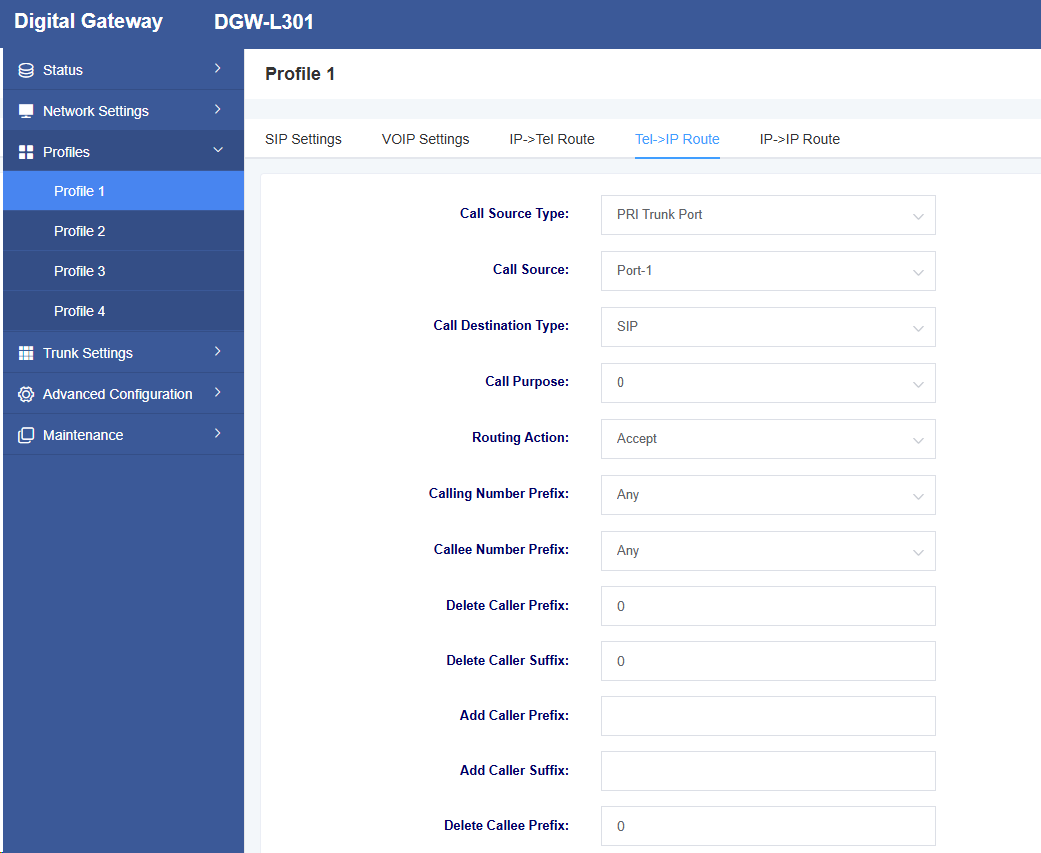
Table 4-4-1 TEL->IP Routing Parameter Description
| Option | Description |
| Routing Failed Call Destination Type | Whether enable routing failed call destination |
| Routing Failed Call Destination | Destination for calls that fail |
| Call Source Type | Call source device type |
| Call Source | Call source device |
| Call Destination Type | Destination type |
| Call Purpose | Call purpose |
| Routing Action | Reject or Allow |
| Calling Number Prefix | Set Calling Number Prefix Type |
| Callee Number Prefix | Set Callee Number Prefix Type |
| Delete Caller Prefix | Delete Calling Number Prefix |
| Delete Caller Suffix | Delete Caller number Suffix |
| Add caller Prefix | Add caller number prefix |
| Add caller Suffix | Add caller Suffix |
| Delete callee prefix | Delete callee number prefix |
| Delete callee prefix | Delete callee nubmer prefix |
| Add Callee prefix | Add callee prefix |
| Add Callee Suffix | Add callee suffix |
4.5 IP->IP Routing
On this page, you can configure related routing settings.
Figure 4-5-1 IP->IP Routing
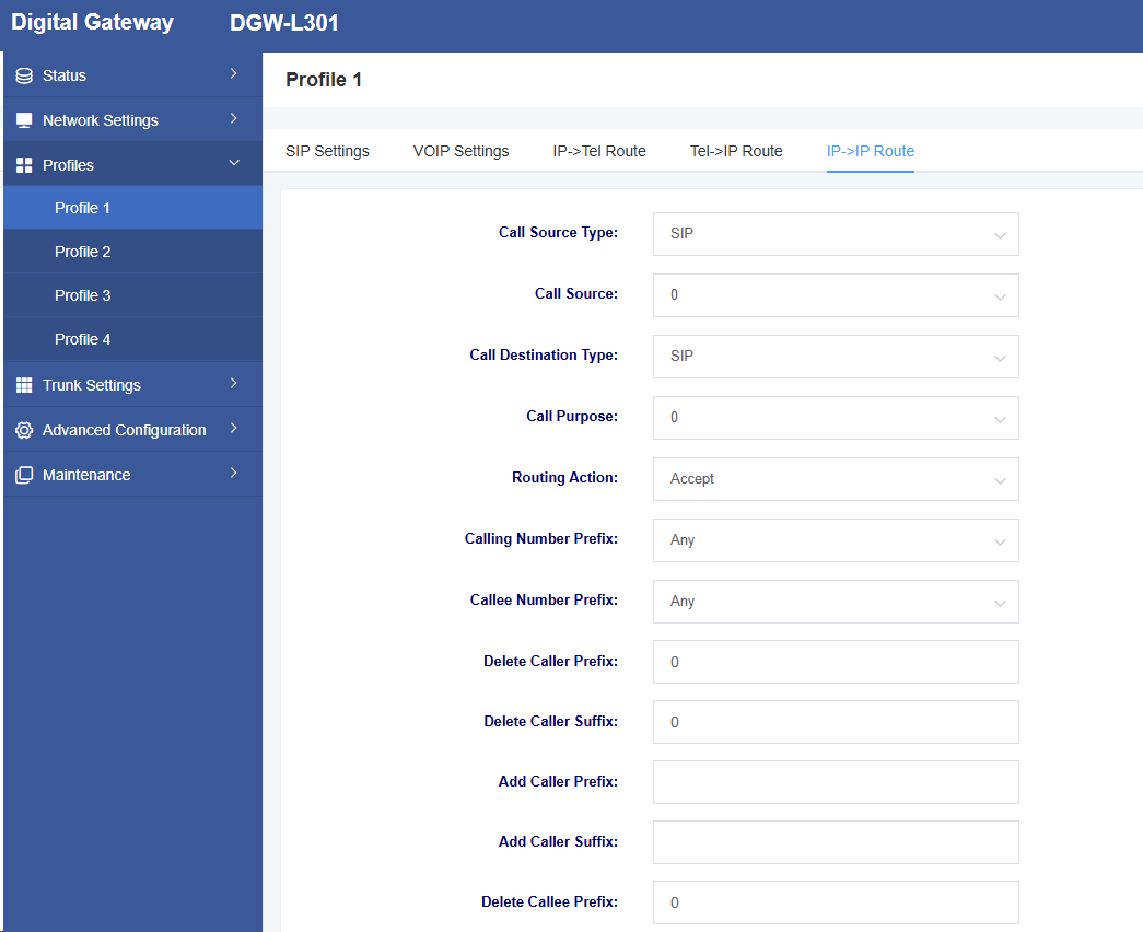
Table 4-5-1 IP->IP Routing Parameter Description
| Option | Description |
| Routing Failed Call Destination Type | Whether enable routing failed call destination |
| Routing Failed Call Destination | Destination when the call fails |
| Call Source Type | Call source device type |
| Call Source | Call source device |
| Call Destination Type | Destination type |
| Call Destination | Call destination |
| Routing Action | Reject or Allow |
| Calling Number prefix | Set calling number prefix type |
| Callee Number prefix | Set callee number prefix type |
| Delete caller prefix | Delete caller number prefix |
| Delete caller Suffix | Delete caller number suffix |
| Add caller prefix | Add Caller number Prefix |
| Add Caller Suffix | Add Caller nubmer Suffix |
| Delete Callee Prefix | Delete Callee number Prefix |
| Delete Callee Suffix | Delete Callee Suffix |
| Add Callee Prefix | Add Callee Prefix |
| Add Callee Suffix | Add suffix to callee number |
5 Trunk Settings
On this page, you can configure trunk type settings.
5.1 SIP Trunk
Figure 5-1-1 Add SIP Trunk Page
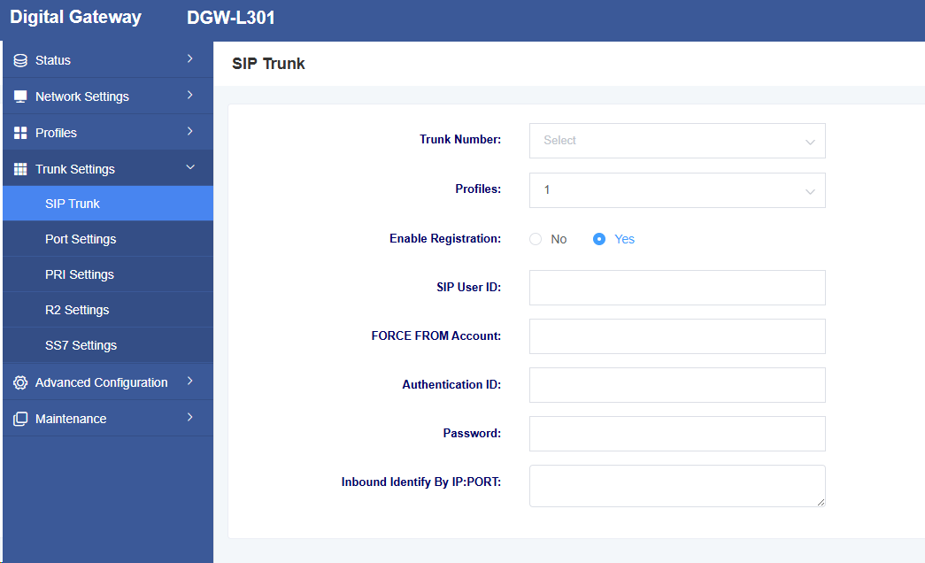
Table 5-1-1 SIP Trunk Page Parameter Description
| Option | Description |
| Trunk Number | Customize the trunk number |
| Template | Select the template settings to use |
| Enable Registration | Select whether to enable registration settings |
| SIP User ID | Set the trunk name |
| FROM Mandatory Account | Set the FROM mandatory account |
| Authentication ID | The authentication ID corresponding to this SIP user ID |
| Password | Password corresponding to the Authentication ID |
| IP Direct Routing Table | Set the caller display name |
5.2 Port Settings
Figure 5-2-1 Port Settings
Table 5-2-1 Call Settings Parameter Description
| Option | Description |
| Line Region | Set the line area |
| Interface Type | E1 or T1 type |
| Clock Source | Select clock source |
| PCM Coding | Select encoding format |
| Frame structure | Frame structure type |
| Line Coding | Select line encoding |
| Line compensation | External line represents the cable length from this network interface to the next device. |
| CRC4 | Set the checksum |
| Signaling | Set the signaling type |
| D Channel | Set the D channel position |
5.3 PRI Settings
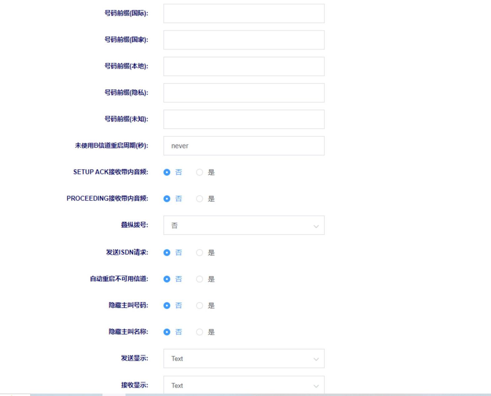
Figure 5-3-1 PRI Settings
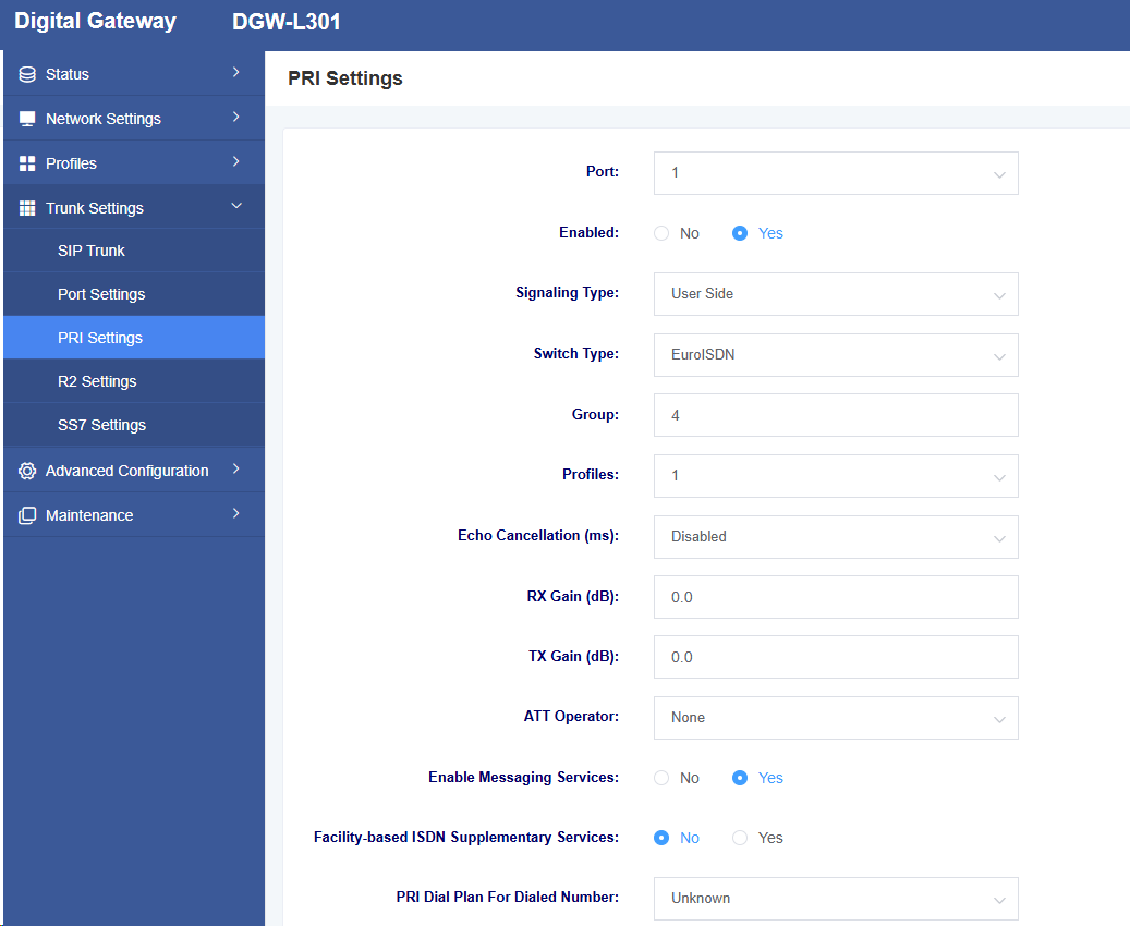
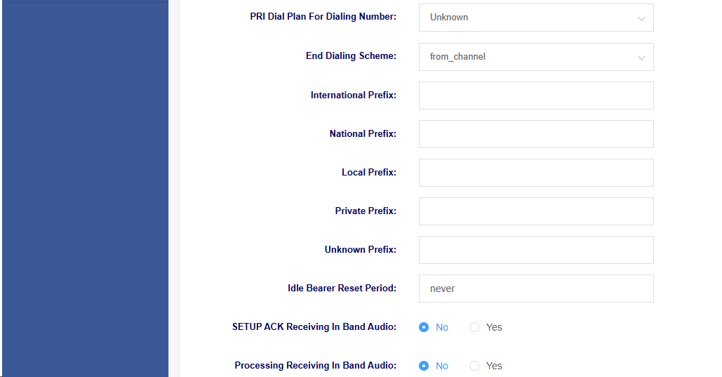
Table 5-3-1 Call Settings Parameter Description
| Option | Description |
| Port | Select port |
| Enable | Enable or disable |
| Signaling type | Select signaling type |
| Switching type | Select switch type |
| Group | Set Group Number |
| Profiles | Select profiles to use |
| Echo cancellation | Whether to enable echo cancellation |
| RX gain | Set RX gain |
| TX gain | Set TX gain |
| ATT operator | Select ATT operator network special parameters |
| Enable Message Service | Whether to enable message service |
| Facility-based ISDN Supplementary Services | Select facility-based ISDN supplementary services |
| PRI Dial Plan For Dialed Numbe | Select PRI dial plan for dialed numbe |
| PRI Dial Plan For Dialing Number | Select PRI dial plan for dialing number |
| End Dialing Scheme | Select end dialing scheme |
| International Prefix | Set international prefix |
| National Prefix | Set national Prefix |
| Local Prefix | Set local prefix |
| Private Prefix | Set private prefix |
| Unknown Prefix | Set unknown prefix |
| Idle Bearer Reset Period | Select idle bearer reset period: |
5.4 R2 settings
Figure 5-4-1 R2 settings
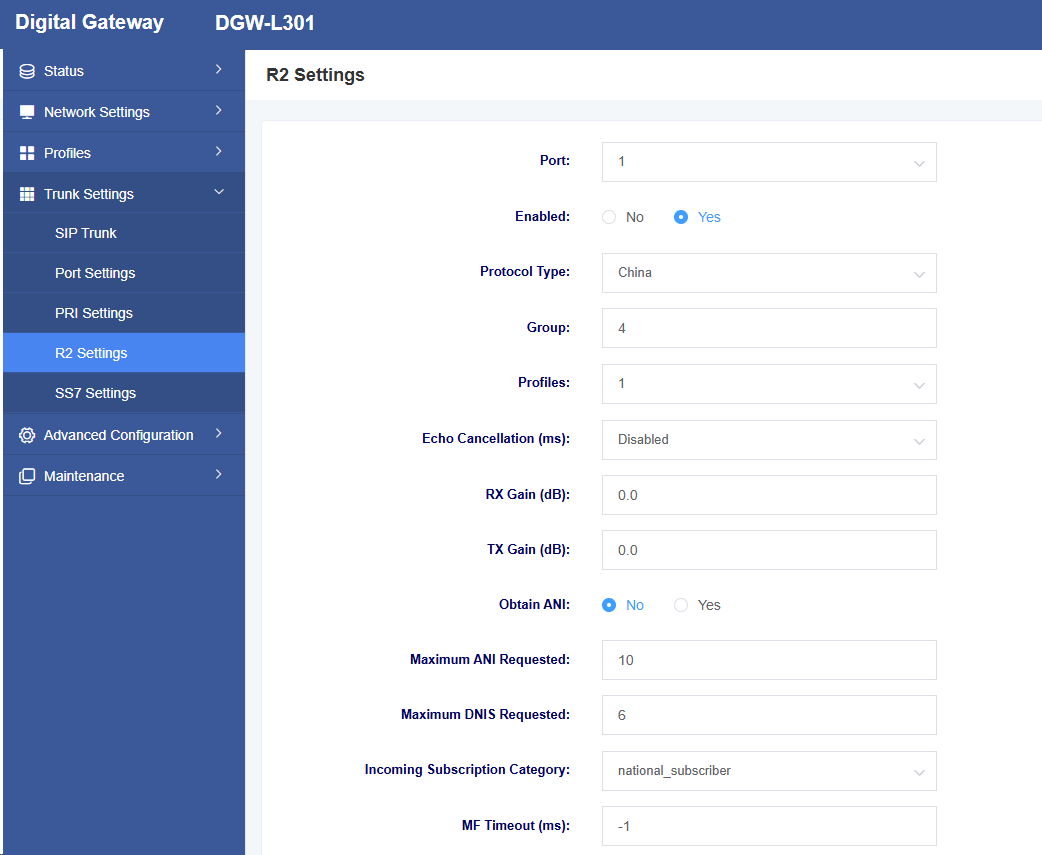
| Option | Description |
| Port | Select port |
| Enable | Whether to enable port |
| Protocol type | Select protocol type |
| Grouping | Set the group |
| Profiles | Select the profiles to use |
| Echo Cancellation | Enable echo cancellation |
| RX Gain | Set the receive gain |
| Tx Gain | Set the transmit gain |
| Obtain ANI | Obtain ANI before obtaining DNIS |
| Maximum ANI Requested | Maximum ANI digit count requested |
| Maximum DNIS requested | Maximum DNIS digits requested |
| Call subscription | Call subscription category |
| MF timeout | MF timeout duration |
| Pulse timeout | Pulse timeout duration |
| Skip Request For Caller category and ANI | Skip request caller category and ANI |
| Support Double Answer | Whether to support dual answer |
5.5 SS7 Settings
Figure 5-5-1 SS7 Settings

Table 5-5-1 SS7 Parameter Description
| Option | Description |
| Link Set | Select link set |
| Profiles | Set profiles |
| Point Format | Select Point Format |
| Source Point Code | Set source point code |
| Destination Point Code | Set destination point code |
| Enable End-Of-Pulsing | Whether to enable End-Of-Pulsing |
| Incoming Reply Signal | Select incoming reply signal |
| Outbound Routing Strategy | Select outbound routing strategy |
| Sub Business Type | Select sub business type |
| Action | Edit or not |
6. Advanced Configuration
6.1 Fax Parameters
On this page, you can configure fax-related parameters.
Figure 6-1-1 Fax Parameters
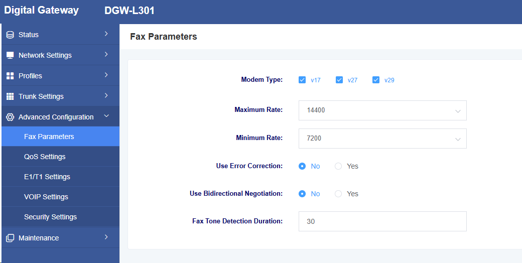
Table 6-1-1 Network Settings Description
| Option | Description |
| Modem Type | Set the supported modem type |
| Maximum Rate | Select the maximum rate supported by the fax |
| Minimum Rate | Select the minimum rate supported by the fax |
| Use Error Correction | Select whether to enable error checking. |
| Use Bidirectional Negotiation | Select whether to enable negotiation. |
| Fax Tone Detection Duration | Set the fax tone detection time. |
6.2 Qos Settings
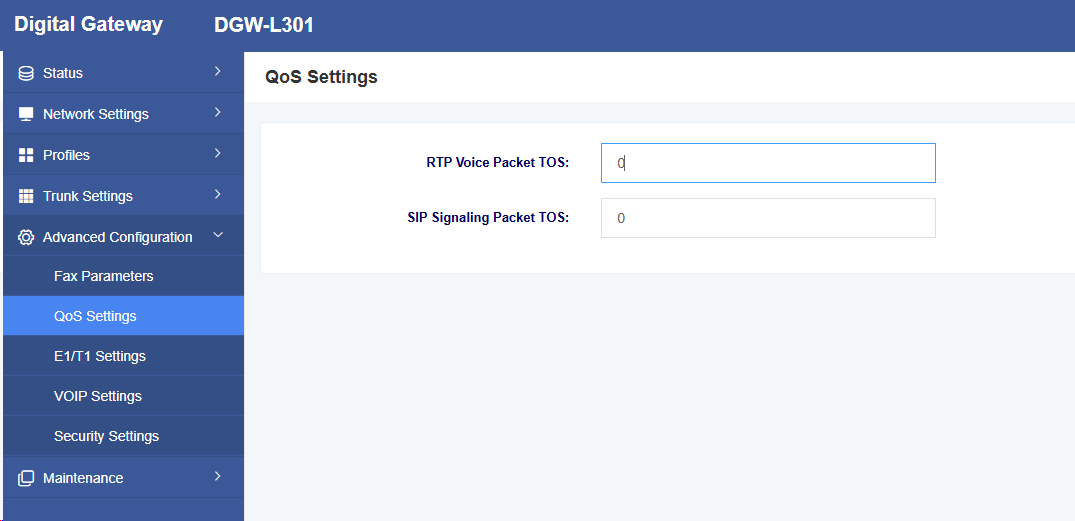
In this interface, you can set the RTP voice message TOS and SIP signaling message TOS.
Figure 6-2-1 Qos Settings Interface
6.3 E1/T1 Settings
In this interface, you can set the relevant parameters for digital lines, such as DTMF and jitter buffer.
Figure 6-3-1 E1/T1 Settings Interface
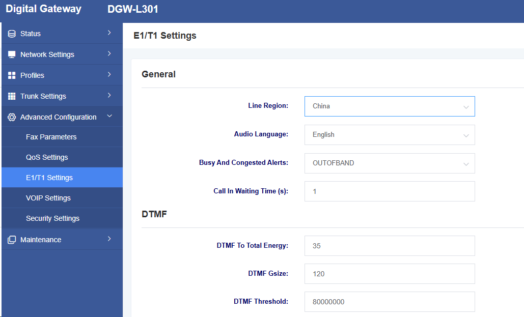
Table 6-3-1 E1/T1 Parameter Description
| Option | Description |
| Line Region | Select the region where the line is located |
| Audio Language | Select the language for audio prompts |
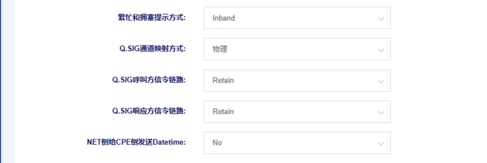
| Busy And Congested Alerts | Select the mode for generating BUSY and CONGESTION notifications |
| Adjust the energy ratio coefficient |
Figure 6-3-2 E1/T1 Settings Interface
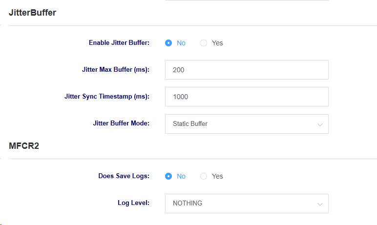
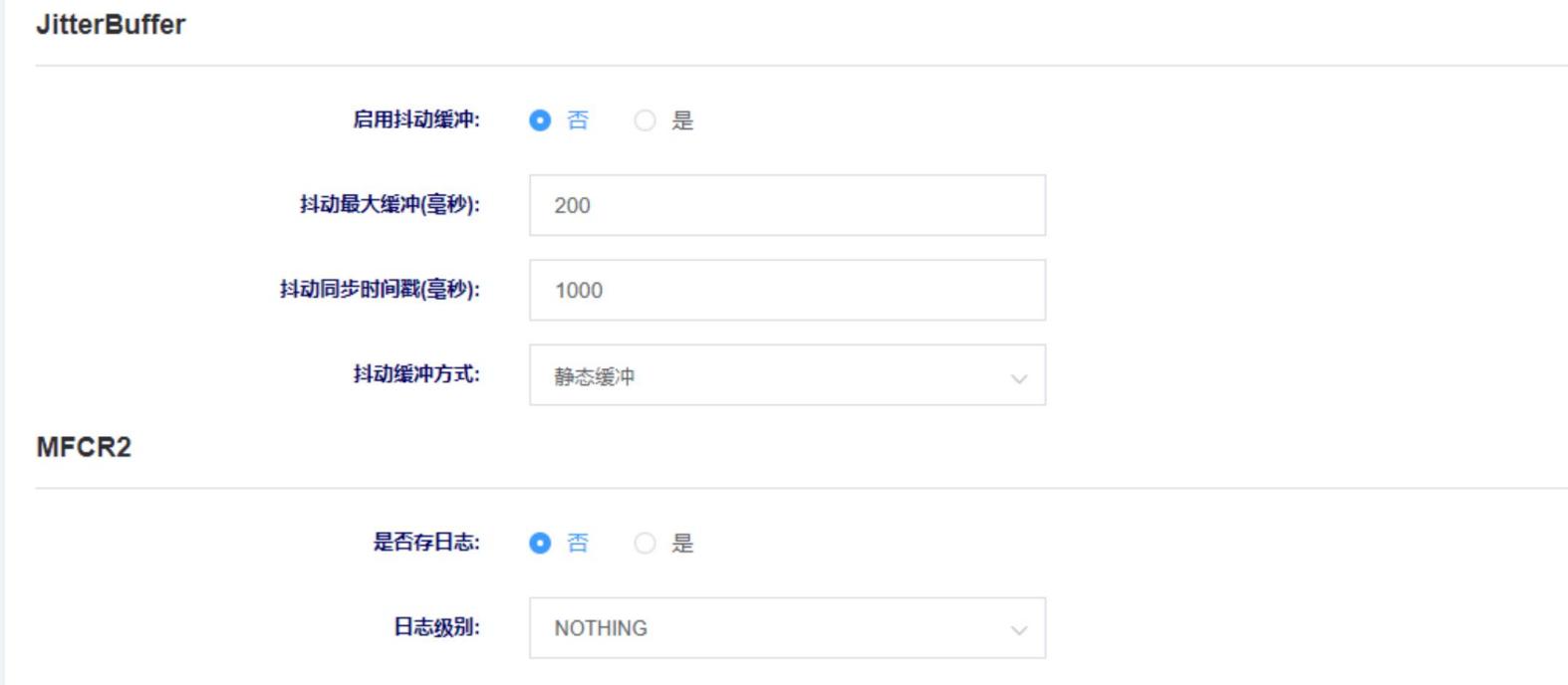
Table 6-3-2 E1/T1 Settings Parameter Description
| Option | Description |
| Enable Jitter Buffer | Select whether to enable jitter buffering |
| Jitter Buffer Mode | Select the jitter buffer mode |
| Jitter Sync Timestamp (ms) | Set the jitter synchronization timestamp |
| Jitter Max Buffer | Set the maximum jitter buffer |
| Does Save Logs | Enable logging |
| Log level | Set the log level |
6.4 VOIP Settings
On this page, you can configure VOIP-related settings, such as call settings and session settings.
Figure 6-4-1 VOIP Settings
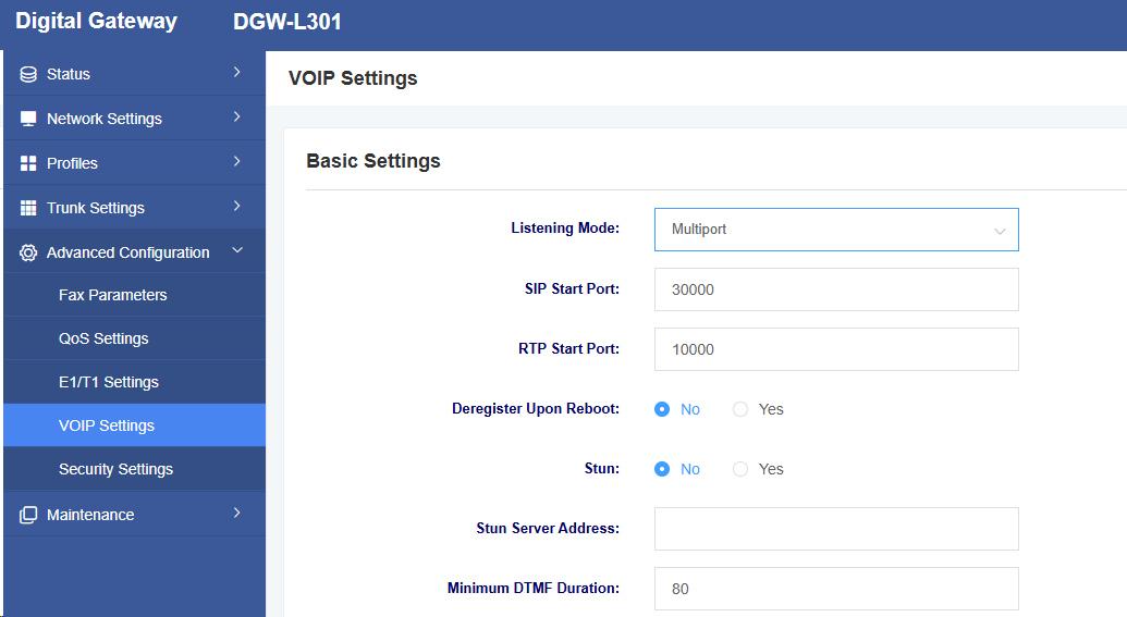
Table 6-4-1 VOIP Settings Parameter Description
| Option | Description |
| Listening Mode | Select listening mode, with options for multi-port and single-port |
| SIP Start Port | Set the starting port for SIP |
| RTP starting port | Set the starting port for RTP |
| Deregister upon reboot | Select whether to unregister upon reboot |
| STUN | Select whether to enable STUN |
| STUN server address | Set the STUN server address |
| Minimum DTMF duration | Set the minimum DTMF duration |
Figure 6-4-2 VoIP Settings
Table 6-4-2 VoIP Settings Parameter Description
| Option | Description |
| T1 Timeout | Set the T1 timeout duration |
| T2 Timeout | Set the T2 timeout duration |
| Incoming Call Wait Timeout | Set the call waiting timeout duration |
| Outgoing call waiting timeout | Set the outgoing call waiting timeout duration |
| Maximum call duration | Set the maximum call duration; calls will be disconnected after exceeding this duration |
| Caller ID display priority | Select whether to prioritize displaying the caller ID from the FROM field or the P-Asserted-Identity field |
| User Agent | Set User Agent |
| Do not escape the “#” character | Whether to escape the # character |
Figure 6-4-3 VoIP Settings

Table 6-4-3 VoIP Settings Parameter Description
| Option | Description |
| Session Timer Mode | Select Session Timer Mode |
| Min-SE | Set the minimum session timeout duration |
| Session Timeout Duration | Set Session Timeout Duration |
| G723 Rate | Set G723 Rate |
| iLBC Frame Size | Set iLBC Frame Duration |
6.5 Security Settings
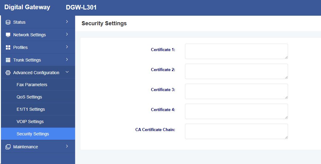
Certificates can be uploaded on this page.
Figure 6-5-1 Security Settings Interface
7 Maintenance
7.1 Automatic Restart
On this page, you can set the automatic restart function, allowing the device to restart according to the set time.
Figure 7-1-1 Restart Page
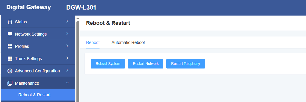
Figure 7-2-1 Automatic Restart Page

7.2 Restore Factory Settings
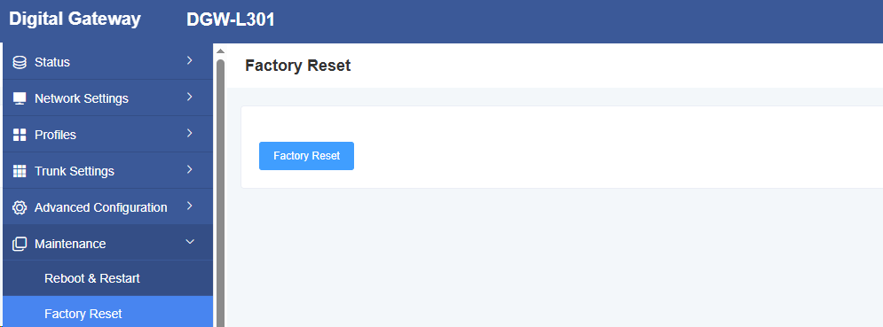
After clicking the Restore Factory Settings button, the device will automatically restart and restore the factory settings.
Figure 7-2-1 Restore Factory Settings Page
7.3 Automatic Deployment
The L301 firmware and upgrade firmware functions can be configured on this page.
Figure 7-3-1 Automatic Deployment Interface
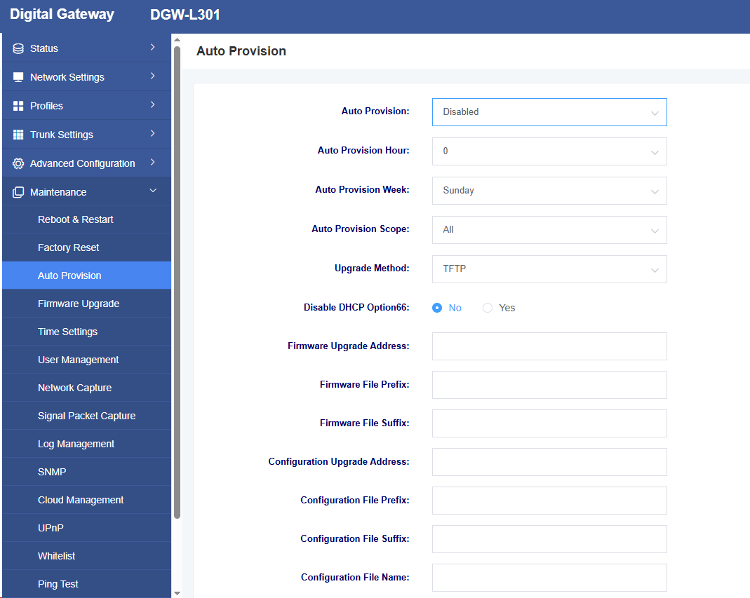
Table 7-3-1 Automatic Deployment Parameter Description
| Option | Description |
| Automatic Deployment | Set the automatic deployment mechanism. You can choose to deploy automatically after each power-on or deploy according to a set time cycle. |
| Automatic Deployment Time | Set the time for deployment. |
| Automatic Deployment Week | Set the day of the week for deployment. |
| Automatic Deployment Scope | Select the scope of automatic deployment. Options include configuration files and firmware updates. |
| Upgrade Method | Select the automatic deployment upgrade method, supporting TFTP, HTTP, and HTTPS |
| Disable DHCP Option 66 | Select whether to enable DHCP Option 66 to obtain files |
| Options | Description |
| Option | Description |
| Firmware Upgrade Address | Set the firmware upgrade path |
| Firmware file prefix | Set the prefix for the firmware file |
| Firmware file suffix | Set the suffix for the firmware file |
| Configuration upgrade address | Set the path for configuration upgrades |
| Configuration file prefix | Set the prefix for the configuration file |
| Configuration file suffix | Set the configuration file suffix |
| Upload configuration | Upload configuration file |
| Download configuration | Download the current configuration file of the device |
File names must be modified according to the rules. The main controller firmware file name rule is (pre)(firmware model).img(post), and the interface board firmware file name rule is
(pre)ixu(mac).img(post), and the configuration file name rule is (pre)cfg(mac)(post). “pre” is the prefix, and “post” is the suffix; both can be left blank.
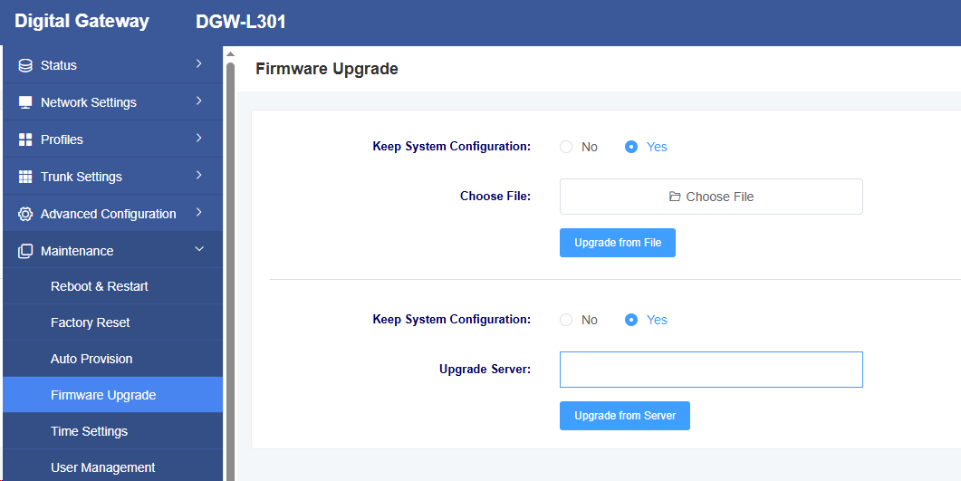
7.4 Firmware Upgrade
On this page, you can perform a firmware upgrade. Select the corresponding firmware type and upload the file to proceed with the upgrade. You can choose whether to retain the system configuration. If you do not retain the system configuration, the device will clear the system configuration after the upgrade.
Figure 7-4-1 Firmware Upgrade
7.5 Time Settings
On this page, you can configure the device’s time settings. Users can set the time zone and specify an NTP server address for automatic time synchronization.
Figure 7-5-1 Time Settings
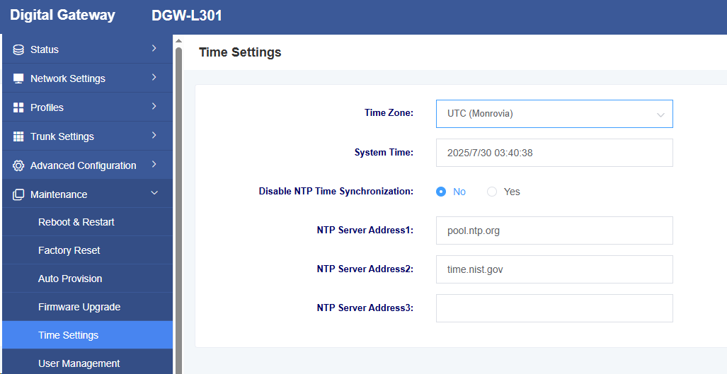
Table 7-5-1 Time Settings Parameter Description
| Option | Description |
| Time Zone | Set the device’s time zone |
| System Time | Display the system time |
| Enable NTP Time Synchronization | Select whether to enable NTP time synchronization |
| NTP Server Address | Set the NTP server address |
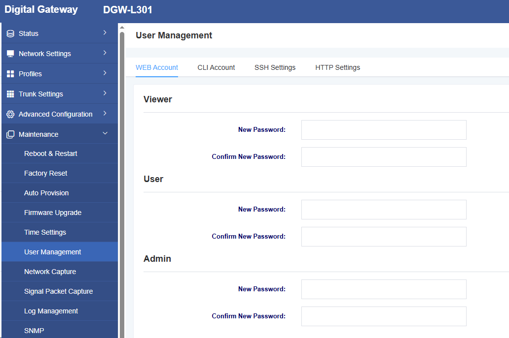
7.6 User Management
The L301 supports different user roles for login, with varying permissions. On the User Management page, you can modify passwords, enable/disable SSH functionality, and configure HTTP settings for different roles.
Figure 7-6-1 User Management
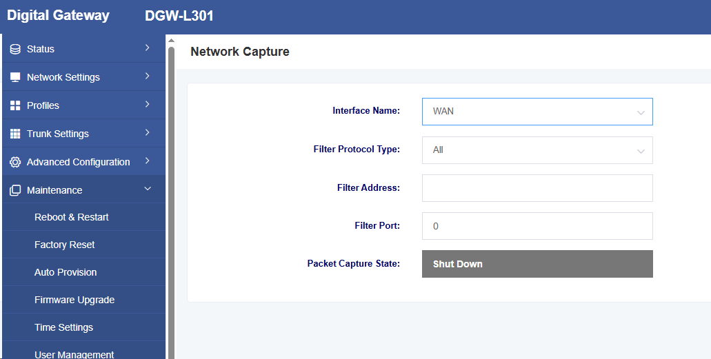
7.7 Network Packet Capture
L301 can conveniently locate network issues. Users can define the capture interface, select protocol types, addresses, and ports on this page.
Figure 7-7-1 Network Packet Capture
7.8 Signaling Packet Capture
L301 can perform signaling packet capture.
Figure 7-8-1 Signaling Packet Capture

7.9 Log Management
In the log management interface, you can set the log server address and port, as well as select the kernel log level, to facilitate technical analysis of device logs.
Figure 7-9-1 Log Management
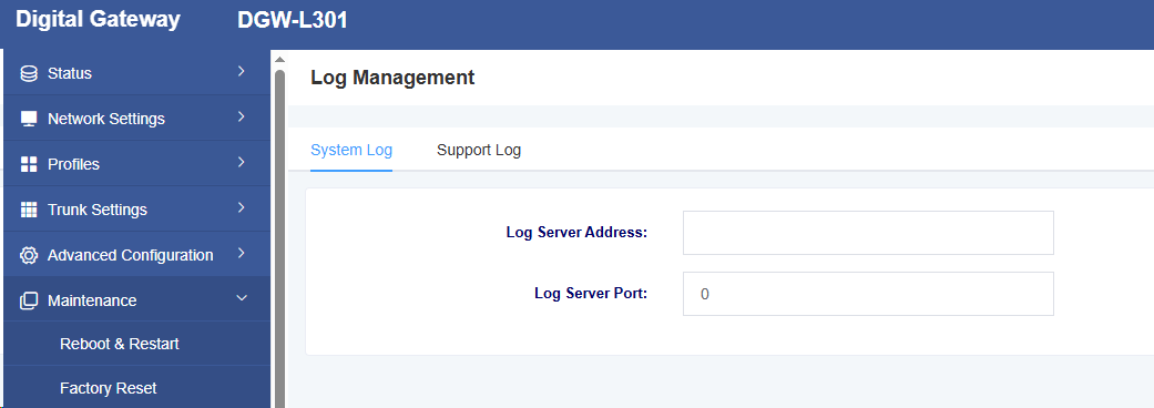
Figure 7-9-2 Log Support Interface
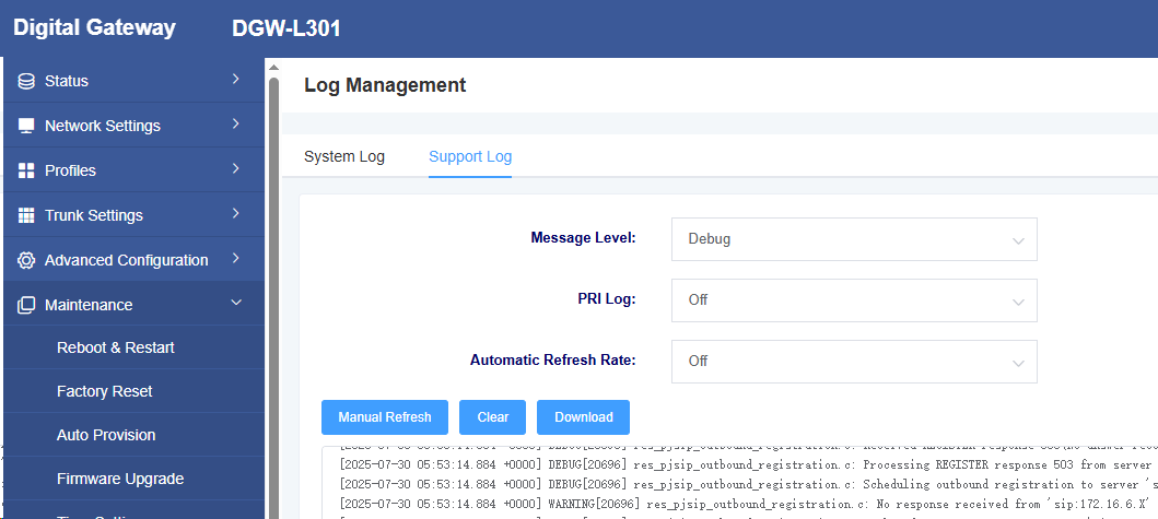
Syslog is commonly referred to as system logs or system records and is a standard used to transmit log messages over a TCP/IP network. This term is often used to refer to the actual syslog protocol or the applications or databases that send syslog messages. The syslog protocol is a master-slave protocol: the syslog sender transmits a small text message (less than 1024 bytes) to the syslog receiver. The receiver is typically named
“syslogd,” “syslog daemon,” or syslog server. System log messages can be transmitted using the UDP protocol and/or the TCP protocol.
Syslog Level Overview:
• EMERG: Failure
• ALERT: Warning
• CRIT: Requires immediate attention
• ERROR: Error conditions that prevent the tool or certain subsystem components from functioning properly
• WARNING: Warning information
• NOTICE: Important general conditions
• INFO: Information
• DEBUG: Additional information not related to function conditions or issues
7.10 SNMP
On this page, you can configure SNMP service-related information. The L301 supports SNMPv1 and v2c.
Figure 7-10-1 SNMP
7.11 Cloud Management
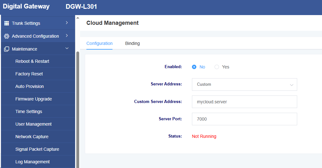
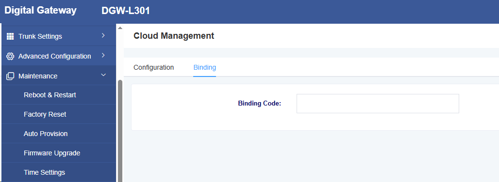
On this page, you can configure information related to cloud management. The L301 supports Openvox’s cloud management functionality. After entering the server address port and binding code, you can manage the device on the cloud management platform.
Figure 7-11-1 Cloud Management Settings

 Figure 7-11-2 Cloud Management Binding
7.12 UPnP
On this page, you can choose whether to enable the UPnP function. After enabling it, the server can automatically search for and manage the local device.
Figure 7-12-1 UPnP Settings

7.13 Whitelist
On this page, you can configure whitelist-related information. After configuration, only IP addresses in the whitelist can access the device.
Figure 7-13-1 Whitelist Settings

7.14 Ping Test
On this page, you can use the ping command to test network connectivity.
Figure 7-14-1 Ping Test

7.15 Tracert Test
On this page, you can use the tracert command to test network connectivity.
Figure 7-15-1 Tracert Test

7.16 DNS Test
On this page, you can perform tests on specified DNS servers.
Figure 7-16-1 DNS Test

7.17 Port Recording
On this page, you can select specific ports for recording to troubleshoot issues.
Figure 7-17-1 Port Logging


